> For the complete documentation index, see [llms.txt](https://carloss-organization-4.gitbook.io/tech/llms.txt). Markdown versions of documentation pages are available by appending `.md` to page URLs; this page is available as [Markdown](https://carloss-organization-4.gitbook.io/tech/ecus/zynq_documents/zynq-qi-dong-liu-cheng.md).
# \[ZYNQ] 启动流程
## \[Embedded] ZYNQ-UltraScale+的启动流程
ZYNQ UltraScale+ 是一种SoC设计,主要包含下面的片上系统:
* Quad-core Arm® **Cortex™-A53-based** Application Processing Unit (APU)
* Dual-core Arm **Cortex-R5F-based** Real-Time Processing Unit (RPU)
* Arm Mali™-400 **MP2 based Graphics Processing Unit (GPU)**
* Dedicated **Platform Management Unit (PMU**) and **Configuration Security Unit (CSU)**
* List of high-speed peripherals, including display port and SATA


 >
> LPD(Contains the ARM Cortex-R5 real-time processor unit (RPU), theplatform management unit (PMU), and the configuration security unit (CSU), aswell as the remaining on-chip peripherals.)要先于FPD(Contains the ARM Cortex-A53application processor unit (APU) as well as a number of peripherals typicallyused by the APU.)
#### 2.1.2 Disabling FPD in Boot Sequence
Perform the following to avoid an FPD lockout, where FPD Power is applied momentarily:
* Apply the power until the completion of bootROM execution.
* To power down the FP during FSBL execution, set FPD bit '22' of PMU\_GLOBAL REQ\_PWRDWN\_STATUS register.
* To bring the FP domain up in a later stage of the boot process, set the PMU\_GLOBAL REQ\_PWRUP\_STATUS bit to '22’.
Perform the following in cases where the FPD power is not applied before the FSBL boots
1. Power up the R5.
2. A register is set indicating the FPD is locked pending POR as the reset or clear sequence cannot execute on the FPD.
3. R5 can read the FP locked status from PMU\_GLOBAL REQ\_ISO\_STATUS register bit ‘4’.
4. At this stage, PMU\_GLOBAL REQ\_PWRUP\_STATUS bit '22' will not be set.
5. To bring the FPD node back up, power must be supplied to the node and a POR needs to be issued.
#### 2.1.3 Setting FSBL Compilation Flags
You can set compilation flags using the C/C++ settings in the Vitis FSBL project, as shown in the following figure:
Note: There is no need to change any of the FSBL source files or header files to include these flags.

编译选项提供一个shrink size的功能:

关于debug调试输出有以下编译选项:

#### 2.1.4 Fallback and MultiBoot Flow (golden image search)
根据上面的流程图,无论是引导失败还是secure boot失败,都会走向fallback的流程,ZYNQ设计fallback的功能,我们可以根据CSU的配置,让CSU来寻找正确的image来加载,查找规则如下:
* bootrom寻找一个正确的image是通过image id 一个字符串来寻找的(这个id在flash的32KB偏移量的位置)
* 找到正确的索引之后,来验证header的checksum值;
* 如果checksum是正确的,bootrom就会加载这个image

因此,要实现这个技术就必然允许超过一个image在flash中。除此之外还要在Multi boot中进行配置:
In MultiBoot:
* CSU ROM or FSBL or the user application must initiate the boot image search to choose a different image from which to boot.
* To initiate this image search, CSU ROM or FSBL updates the MultiBoot offset to point to the intended boot image, and generates a soft reset by writing into the CRL\_APB register.

这个过程可以描述为:
* 最开始,CSU bootrom加载0x0的boot image;
* 如果这个image做secure boot失败或者损坏,CSU bootrom会搜寻下一个image在32kb的位置(0x0000\_8000)的位置。
* 如果在这个位置并没有一个识别头,或者CSU bootrom继续向下一个offset搜寻(0x0001\_8000)的位置。
* 直到找到一个正确的image或者到了寻找的地址范围。
范围如下:

无论是non-secure 或者secure的都是支持fallback规则。
boot image 的格式:
header的格式:
### 2.2 FSBL stage
PMU和CSU在软件上程序员只是需要关注原理和配置(模式)即可,进入到FSBL阶段,就需要程序员来进行编译和程序的修改了。
FSBL在认证和解密之后(如果是能了secure boot),此时FSBL被CSU加载进入OCM中,并且从CSU中接手执行权限。FSBL使用FPGA的bitstream进行配置,并且FSBL需要加载Standalone(SA,裸机程序)或SSBL(Second stage boot loader)的image从(NAND/SD/EMMC/QSPI)加载到RAM中(DDR/TCM/OCM)。FSBL需要将R5F核或者A53核解除复位状态。FSBL同样支持多个分区(每一个分区可以是一个image,或者一个bitstream)。如果使能secure boot,每一个分区需要被认证或者解密。
> 注意:如果在创建一个FSBL过程中,我们始终有一种意识是OCM的大小仅仅256kb,除去CSU使用的部分,给我们留下的大小大概是170kb。然而,使用USB启动模式的时候要确认PMU firmware是被FSBL加载而不是CSU 的bootrom。因为usb的超过了CSU的打消了。
> 在未加密的情况下,用户可以加载bitstream:
>
> * By default, the FSBL\_PL\_LOAD\_FROM\_OCM\_EXCLUDE\_VAL value is set to 0 in xfsbl\_config.h, making the bitstream copy and load from DDR in the non-encrypted cases.
> * By setting the FSBL\_PL\_LOAD\_FROM\_OCM\_EXCLUDE\_VAL value to 1, the user can ensure that bitstream is loaded from OCM in chunks and not from DDR
> * if DDR is not present in the design, the bitstream is loaded from OCM irrespective of the FSBL\_PL\_LOAD\_FROM\_OCM\_EXCLUDE\_VAL value.
#### 2.2.1 create FSBL project
这部分在文档中介绍了:
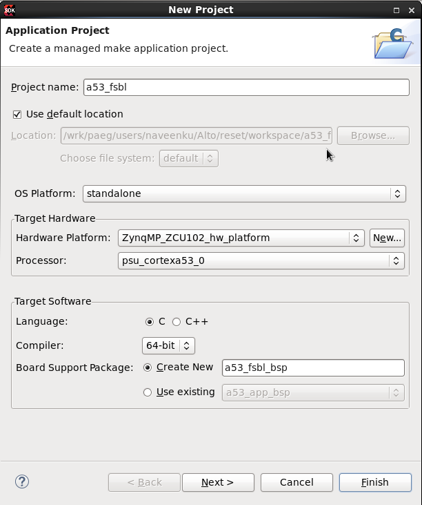
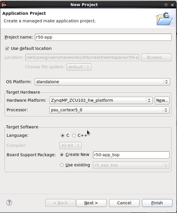
To create a new Zynq UltraScale+ MPSoC FSBL application in the Vitis software platform, do the following:
1. Click File > New > Application Project. The New Application Project dialog box appears.
2. In the Project Name field, type a name for the new project.
3. Select the location for the project. To use the default location as displayed in the Location field, leave the Use default location check box selected. Otherwise, click to deselect the check box, then type or browse to the directory location.
4. Select Create a new platform from hardware (XSA). The Vitis IDE lists the all the available pre-defined hardware designs.
5. Select any one hardware design from the list and click Next.
6. From the CPU drop-down list, select the processor for which you want to build the application. This is an important step when there are multiple processors in your design. In this case you can either select psu\_cortexa53\_0 or psu\_cortexr5\_0.
7. Select your preferred language: C.
8. Select an OS for the targeted application.
9. Click Next.
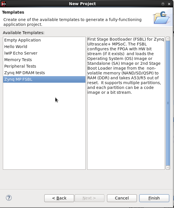
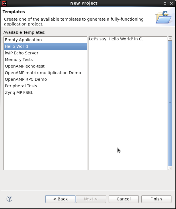
10. In the Templates dialog box, select the Zynq UltraScale+ MPSoC FSBL template.
11. Click Finish to create your application project and board support package (if it does not exist).
请注意第6步骤的多核场景,如果在应用中使能了多核的场景,我们在boot中也该做相应的配置,否则可能会block多核的正常使用。
#### 2.2.2 FSBL LowLevel
一个合格的FSBL,必须有以下的能力:
FSBL operation includes the following four stages:
* Initialization
* Boot device initialization
* Partition loading
* Handoff
这部分我们暂时不研究了。
## 3. Golden image example
Golden image是存在非易失性存储上的备用的image,当主引导image损坏时,ZYNQ的Multiboot机制可以引导该image。其设计目的是:在 ZYNQ 产品出厂后,如果要更新功能,像手机那样的下载更新,如果更新失败就会变成“砖”。Multiboot 的存在就是为了解决这一问题。将 ZYNQ 产品的出厂引导文件放在 QSPI FLASH / SD Card的可引导的末端位置,这时的出厂引导文件就做 Golden Image,后面更新功能的时候将更新的引导文件放在 QSPI FLASH / SD Card的可引导的前端,也就是说 ZYNQ 启动后,先检索到更新的引导文件,然后引导其启动,如果该文件更新失败,就会从检索到的 Golden Image(出厂引导文件)启动,免得更新失败造成产品不可用。
根据2.1.4小节,可以总结为ZYNQ的multiboot机制有以下特点:
1. Golden Image Search 当在闪存的底部(起始位置)没有找到有效的头文件时,BootROM 就会发起 Search 请求。BootROM 将在每 32KB 的偏移量处开始搜索一个有效的头。这种机制很慢,但很可靠。
2. BootROM Multiboot 这是由 FSBL 发起的,也就是 user。如果 BootROM 找到了一个有效的头文件并交给 FSBL,那么 FSBL 可以加载 Multiboot 寄存器并发出软复位。软复位后,BootROM 将使用 Multiboot 寄存器的地址来读取 BootROM 头文件。例如,当用户想要运行自检和诊断,然后跳转到实际的应用程序时,就会使用这种机制。
3. FSBL Fallback 为了从错误条件中恢复,FSBL 做了一个回退(Fallback),使 BootROM 能够加载另一个可引导镜像 (最初出现并处于已知良好状态的 golden image),如果该镜像存在于闪存中。FSBL 更新一个 Multiboot 寄存器并进行软复位,以便 BootROM 执行并加载下一个当前有效的镜像。无论是否软复位,FSBL 都可能发生回退。
### 3.1 使用 FSBL Fallback 来进行 Multiboot(non-sec)
#### 3.1.1 用例目的
制作一个non-sec的用例来触发ZYNQ的fallback流程以启动golden image;了解golden image的制作过程;对fallback流程进行验证。
#### 3.1.2 实验方法
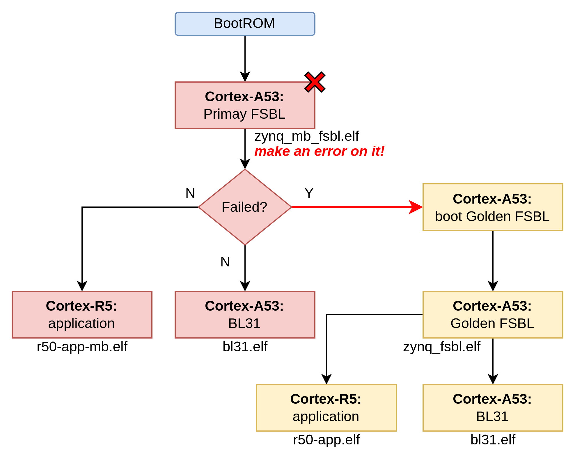
准备两路引导,一路primary引导,另一路是golden引导。在primay引导中,故意制造一个错误,让其引导失败返回,验证ZYNQ是否进入golden image路径。
在primary引导中:
* 设定`zynq_mb_fsbl.elf`文件为primary FSBL (故障固件);
* 设定`r50-app-mb.elf`为 cortex-R5核心的普通应用程序(设定输出log为"primary image",以此识别当前引导所在路径primary image);
* 设定`bl31.elf`为 TF-A 引导固件。
在Golden引导中:
* 设定`zynq_fsbl.elf`文件为primary FSBL (好用的固件);
* 设定`r50-app.elf`为 cortex-R5核心的普通应用程序(设定输出log为"golden image",以此识别当前引导所在路径为golden image);
* 设定`bl31.elf`为 TF-A 引导固件(以primary为同一个文件)。
实验判定:当ZYNQ启动之后,串口输出log为"golden image" 证明启动进入goledn image成功。
#### 3.1.3 实验过程
我们要生成:
* zynq\_mb\_fsbl.elf (故障的fsbl引导)
* r50-app-mb.elf (输出log为 primary image的应用)
* zynq\_fsbl.elf (完整的fsbl引导)
* r50-app.elf (输出log为 golden image的应用)
**3.1.3.1 创建vitis FSBL工程**
在vitis创建FSBL工程,以生成:
* zynq\_mb\_fsbl.elf (故障的fsbl引导)
* zynq\_fsbl.elf (完整的fsbl引导)
**生成zynq\_fsbl.elf**
zynq\_fsbl是一个完整的golden image,因此不需要对工程进行修改,直接编译,编译出的二进制elf文件命名为:zynq\_fsbl.elf 留用。
**生成zynq\_mb\_fsbl.elf**
接着,我们需要生成一个故障的zynq\_mb\_fsbl.elf,可以在其源代码中,修改某个节点返回值,插桩制造一个错误。
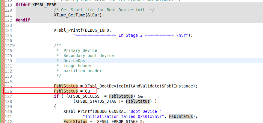
我这里在136行,故意插入一个错误的代码,让其进入Fallback流程。然后对项目进行编译。生成的编译之后的elf文件,命名为:zynq\_mb\_fsbl.elf 留用。
**3.1.3.2 创建Cortex-R5 hello world 应用**
在vitis创建Cortex-R5工程,以生成:
* r50-app-mb.elf (输出log为 primary image的应用)
* r50-app.elf (输出log为 golden image的应用)
**r50-app.elf**
在工程中修改main函数中的log输出,标识是golden image:
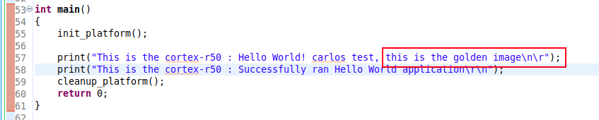
编译出来的elf文件,重命名为r50-app.elf 留用。
**r50-app-mb.elf**
在工程中修改main函数中的log输出,标识是primary image:
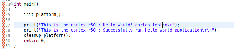
编译出来的elf文件,重命名为r50-app-mb.elf 留用。
**3.1.3.3 建立primary引导**
该步骤需要使用bootgen工具,其bif为:
```
the_ROM_image:
{
[bootloader, destination_cpu=a53-0] images/zynq_mb_fsbl.elf
[pmufw_image] images/xpfw.elf
[destination_cpu=a53-0] images/bl31.elf
[destination_cpu=a53-0] images/u-boot.elf
[destination_cpu=r5-0] images/r50-app-mb.elf
}
```
生成命令:
```bash
bootgen -image bif/boota53_mb.bif -arch zynqmp -w -o i boot.bin
```
**3.1.3.4 建立golden引导**
该步骤需要使用bootgen工具,其bif为:
```
the_ROM_image:
{
[bootloader, destination_cpu=a53-0] images/zynq_fsbl.elf
[pmufw_image] images/xpfw.elf
[destination_cpu=a53-0] images/bl31.elf
[destination_cpu=a53-0] images/u-boot.elf
[destination_cpu=r5-0] images/r50-app.elf
}
```
生成命令:
```bash
bootgen -image bif/boota53.bif -arch zynqmp -w -o i boot0001.bin
cp -r boot0001.bin boot0002.bin
```
**3.1.3.5 拷贝到SD卡 boot分区**
boot.bin 和 boot0001.bin 和 boot0002.bin 复制到SD卡的boot分区,大功告成。
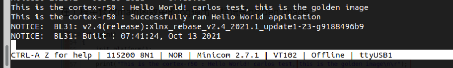
#### 3.1.3 实验结果
### 3.2 使用 FSBL Fallback 来进行 Multiboot(secure)
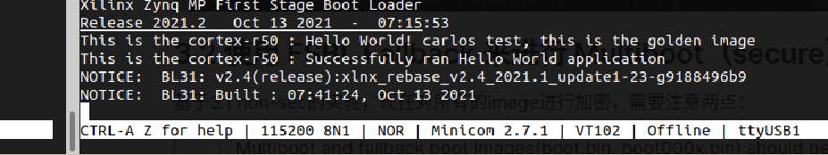
基于3.1 non-sec的实验,现在对所有的image进行加密,需要注意两点:
> 1. Multiboot and fallback boot images(boot.bin, boot000x.bin) should be made with using same key in encryption for Secure boot mode.
2. Multiboot and fallback boot images(boot.bin, boot000x.bin) should be made with using same key in authentication for Secure boot mode.
我们的images还是利用3.1实验中的images:
* zynq\_mb\_fsbl.elf (故障的fsbl引导)
* r50-app-mb.elf (输出log为 primary image的应用)
* zynq\_fsbl.elf (完整的fsbl引导)
* r50-app.elf (输出log为 golden image的应用)
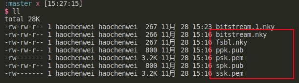
除此之外还需要准备加密的key和签名的私钥:
#### 3.2.1 实验步骤
**3.2.1.1 建立primary引导**
该步骤需要使用bootgen工具,其bif为:
```
the_ROM_image:
{
[pskfile]keys/psk.pem
[sskfile]keys/ssk.pem
[keysrc_encryption] bbram_red_key
[auth_params]spk_id = 0; ppk_select = 0
[fsbl_config] a53_x64, bh_auth_enable
[bootloader, destination_cpu=a53-0, authentication = rsa, encryption = aes, aeskeyfile = keys/fsbl.nky] images/zynq_mb_fsbl.elf
[pmufw_image] images/xpfw.elf
[destination_cpu=a53-0, exception_level=el-3, trustzone, authentication = rsa] images/bl31.elf
[destination_cpu=a53-0, exception_level=el-2, authentication = rsa] images/u-boot.elf
[destination_cpu=r5-0, authentication=rsa, encryption=aes, aeskeyfile = keys/bitstream.nky] images/r50-app-mb.elf
}
```
生成命令:
```bash
bootgen -image bif/boota53_mb.bif -arch zynqmp -w -o i boot.bin
```
**3.2.1.2 建立golden引导**
该步骤需要使用bootgen工具,其bif为:
```
the_ROM_image:
{
[pskfile]keys/psk.pem
[sskfile]keys/ssk.pem
[keysrc_encryption] bbram_red_key
[auth_params]spk_id = 0; ppk_select = 0
[fsbl_config] a53_x64, bh_auth_enable
[bootloader, destination_cpu=a53-0, authentication = rsa, encryption = aes, aeskeyfile = keys/fsbl.nky] images/zynq_fsbl.elf
[pmufw_image] images/xpfw.elf
[destination_cpu=a53-0, exception_level=el-3, trustzone, authentication = rsa] images/bl31.elf
[destination_cpu=a53-0, exception_level=el-2, authentication = rsa] images/u-boot.elf
[destination_cpu=r5-0, authentication=rsa, encryption=aes, aeskeyfile = keys/bitstream.nky] images/r50-app.elf
}
```
生成命令:
```bash
bootgen -image bif/boota53.bif -arch zynqmp -w -o i boot0001.bin
cp -r boot0001.bin boot0002.bin
```
**3.2.1.3 拷贝到SD卡 boot分区**
boot.bin 和 boot0001.bin 和 boot0002.bin 复制到SD卡的boot分区,大功告成。
#### 3.2.2 实验结果
### 3.3 总结
到此,我们完成了non-sec和sec的Golden image的实验。
## Ref
1. [Zynq-UltraScale-Device-Technical-Reference-Manual](https://docs.xilinx.com/r/en-US/ug1085-zynq-ultrascale-trm/Zynq-UltraScale-Device-Technical-Reference-Manual)
>
> LPD(Contains the ARM Cortex-R5 real-time processor unit (RPU), theplatform management unit (PMU), and the configuration security unit (CSU), aswell as the remaining on-chip peripherals.)要先于FPD(Contains the ARM Cortex-A53application processor unit (APU) as well as a number of peripherals typicallyused by the APU.)
#### 2.1.2 Disabling FPD in Boot Sequence
Perform the following to avoid an FPD lockout, where FPD Power is applied momentarily:
* Apply the power until the completion of bootROM execution.
* To power down the FP during FSBL execution, set FPD bit '22' of PMU\_GLOBAL REQ\_PWRDWN\_STATUS register.
* To bring the FP domain up in a later stage of the boot process, set the PMU\_GLOBAL REQ\_PWRUP\_STATUS bit to '22’.
Perform the following in cases where the FPD power is not applied before the FSBL boots
1. Power up the R5.
2. A register is set indicating the FPD is locked pending POR as the reset or clear sequence cannot execute on the FPD.
3. R5 can read the FP locked status from PMU\_GLOBAL REQ\_ISO\_STATUS register bit ‘4’.
4. At this stage, PMU\_GLOBAL REQ\_PWRUP\_STATUS bit '22' will not be set.
5. To bring the FPD node back up, power must be supplied to the node and a POR needs to be issued.
#### 2.1.3 Setting FSBL Compilation Flags
You can set compilation flags using the C/C++ settings in the Vitis FSBL project, as shown in the following figure:
Note: There is no need to change any of the FSBL source files or header files to include these flags.

编译选项提供一个shrink size的功能:

关于debug调试输出有以下编译选项:

#### 2.1.4 Fallback and MultiBoot Flow (golden image search)
根据上面的流程图,无论是引导失败还是secure boot失败,都会走向fallback的流程,ZYNQ设计fallback的功能,我们可以根据CSU的配置,让CSU来寻找正确的image来加载,查找规则如下:
* bootrom寻找一个正确的image是通过image id 一个字符串来寻找的(这个id在flash的32KB偏移量的位置)
* 找到正确的索引之后,来验证header的checksum值;
* 如果checksum是正确的,bootrom就会加载这个image

因此,要实现这个技术就必然允许超过一个image在flash中。除此之外还要在Multi boot中进行配置:
In MultiBoot:
* CSU ROM or FSBL or the user application must initiate the boot image search to choose a different image from which to boot.
* To initiate this image search, CSU ROM or FSBL updates the MultiBoot offset to point to the intended boot image, and generates a soft reset by writing into the CRL\_APB register.

这个过程可以描述为:
* 最开始,CSU bootrom加载0x0的boot image;
* 如果这个image做secure boot失败或者损坏,CSU bootrom会搜寻下一个image在32kb的位置(0x0000\_8000)的位置。
* 如果在这个位置并没有一个识别头,或者CSU bootrom继续向下一个offset搜寻(0x0001\_8000)的位置。
* 直到找到一个正确的image或者到了寻找的地址范围。
范围如下:

无论是non-secure 或者secure的都是支持fallback规则。
boot image 的格式:
header的格式:
### 2.2 FSBL stage
PMU和CSU在软件上程序员只是需要关注原理和配置(模式)即可,进入到FSBL阶段,就需要程序员来进行编译和程序的修改了。
FSBL在认证和解密之后(如果是能了secure boot),此时FSBL被CSU加载进入OCM中,并且从CSU中接手执行权限。FSBL使用FPGA的bitstream进行配置,并且FSBL需要加载Standalone(SA,裸机程序)或SSBL(Second stage boot loader)的image从(NAND/SD/EMMC/QSPI)加载到RAM中(DDR/TCM/OCM)。FSBL需要将R5F核或者A53核解除复位状态。FSBL同样支持多个分区(每一个分区可以是一个image,或者一个bitstream)。如果使能secure boot,每一个分区需要被认证或者解密。
> 注意:如果在创建一个FSBL过程中,我们始终有一种意识是OCM的大小仅仅256kb,除去CSU使用的部分,给我们留下的大小大概是170kb。然而,使用USB启动模式的时候要确认PMU firmware是被FSBL加载而不是CSU 的bootrom。因为usb的超过了CSU的打消了。
> 在未加密的情况下,用户可以加载bitstream:
>
> * By default, the FSBL\_PL\_LOAD\_FROM\_OCM\_EXCLUDE\_VAL value is set to 0 in xfsbl\_config.h, making the bitstream copy and load from DDR in the non-encrypted cases.
> * By setting the FSBL\_PL\_LOAD\_FROM\_OCM\_EXCLUDE\_VAL value to 1, the user can ensure that bitstream is loaded from OCM in chunks and not from DDR
> * if DDR is not present in the design, the bitstream is loaded from OCM irrespective of the FSBL\_PL\_LOAD\_FROM\_OCM\_EXCLUDE\_VAL value.
#### 2.2.1 create FSBL project
这部分在文档中介绍了:
To create a new Zynq UltraScale+ MPSoC FSBL application in the Vitis software platform, do the following:
1. Click File > New > Application Project. The New Application Project dialog box appears.
2. In the Project Name field, type a name for the new project.
3. Select the location for the project. To use the default location as displayed in the Location field, leave the Use default location check box selected. Otherwise, click to deselect the check box, then type or browse to the directory location.
4. Select Create a new platform from hardware (XSA). The Vitis IDE lists the all the available pre-defined hardware designs.
5. Select any one hardware design from the list and click Next.
6. From the CPU drop-down list, select the processor for which you want to build the application. This is an important step when there are multiple processors in your design. In this case you can either select psu\_cortexa53\_0 or psu\_cortexr5\_0.
7. Select your preferred language: C.
8. Select an OS for the targeted application.
9. Click Next.
10. In the Templates dialog box, select the Zynq UltraScale+ MPSoC FSBL template.
11. Click Finish to create your application project and board support package (if it does not exist).
请注意第6步骤的多核场景,如果在应用中使能了多核的场景,我们在boot中也该做相应的配置,否则可能会block多核的正常使用。
#### 2.2.2 FSBL LowLevel
一个合格的FSBL,必须有以下的能力:
FSBL operation includes the following four stages:
* Initialization
* Boot device initialization
* Partition loading
* Handoff
这部分我们暂时不研究了。
## 3. Golden image example
Golden image是存在非易失性存储上的备用的image,当主引导image损坏时,ZYNQ的Multiboot机制可以引导该image。其设计目的是:在 ZYNQ 产品出厂后,如果要更新功能,像手机那样的下载更新,如果更新失败就会变成“砖”。Multiboot 的存在就是为了解决这一问题。将 ZYNQ 产品的出厂引导文件放在 QSPI FLASH / SD Card的可引导的末端位置,这时的出厂引导文件就做 Golden Image,后面更新功能的时候将更新的引导文件放在 QSPI FLASH / SD Card的可引导的前端,也就是说 ZYNQ 启动后,先检索到更新的引导文件,然后引导其启动,如果该文件更新失败,就会从检索到的 Golden Image(出厂引导文件)启动,免得更新失败造成产品不可用。
根据2.1.4小节,可以总结为ZYNQ的multiboot机制有以下特点:
1. Golden Image Search 当在闪存的底部(起始位置)没有找到有效的头文件时,BootROM 就会发起 Search 请求。BootROM 将在每 32KB 的偏移量处开始搜索一个有效的头。这种机制很慢,但很可靠。
2. BootROM Multiboot 这是由 FSBL 发起的,也就是 user。如果 BootROM 找到了一个有效的头文件并交给 FSBL,那么 FSBL 可以加载 Multiboot 寄存器并发出软复位。软复位后,BootROM 将使用 Multiboot 寄存器的地址来读取 BootROM 头文件。例如,当用户想要运行自检和诊断,然后跳转到实际的应用程序时,就会使用这种机制。
3. FSBL Fallback 为了从错误条件中恢复,FSBL 做了一个回退(Fallback),使 BootROM 能够加载另一个可引导镜像 (最初出现并处于已知良好状态的 golden image),如果该镜像存在于闪存中。FSBL 更新一个 Multiboot 寄存器并进行软复位,以便 BootROM 执行并加载下一个当前有效的镜像。无论是否软复位,FSBL 都可能发生回退。
### 3.1 使用 FSBL Fallback 来进行 Multiboot(non-sec)
#### 3.1.1 用例目的
制作一个non-sec的用例来触发ZYNQ的fallback流程以启动golden image;了解golden image的制作过程;对fallback流程进行验证。
#### 3.1.2 实验方法

准备两路引导,一路primary引导,另一路是golden引导。在primay引导中,故意制造一个错误,让其引导失败返回,验证ZYNQ是否进入golden image路径。
在primary引导中:
* 设定`zynq_mb_fsbl.elf`文件为primary FSBL (故障固件);
* 设定`r50-app-mb.elf`为 cortex-R5核心的普通应用程序(设定输出log为"primary image",以此识别当前引导所在路径primary image);
* 设定`bl31.elf`为 TF-A 引导固件。
在Golden引导中:
* 设定`zynq_fsbl.elf`文件为primary FSBL (好用的固件);
* 设定`r50-app.elf`为 cortex-R5核心的普通应用程序(设定输出log为"golden image",以此识别当前引导所在路径为golden image);
* 设定`bl31.elf`为 TF-A 引导固件(以primary为同一个文件)。
实验判定:当ZYNQ启动之后,串口输出log为"golden image" 证明启动进入goledn image成功。
#### 3.1.3 实验过程
我们要生成:
* zynq\_mb\_fsbl.elf (故障的fsbl引导)
* r50-app-mb.elf (输出log为 primary image的应用)
* zynq\_fsbl.elf (完整的fsbl引导)
* r50-app.elf (输出log为 golden image的应用)
**3.1.3.1 创建vitis FSBL工程**
在vitis创建FSBL工程,以生成:
* zynq\_mb\_fsbl.elf (故障的fsbl引导)
* zynq\_fsbl.elf (完整的fsbl引导)


**生成zynq\_fsbl.elf**
zynq\_fsbl是一个完整的golden image,因此不需要对工程进行修改,直接编译,编译出的二进制elf文件命名为:zynq\_fsbl.elf 留用。
**生成zynq\_mb\_fsbl.elf**
接着,我们需要生成一个故障的zynq\_mb\_fsbl.elf,可以在其源代码中,修改某个节点返回值,插桩制造一个错误。

我这里在136行,故意插入一个错误的代码,让其进入Fallback流程。然后对项目进行编译。生成的编译之后的elf文件,命名为:zynq\_mb\_fsbl.elf 留用。
**3.1.3.2 创建Cortex-R5 hello world 应用**
在vitis创建Cortex-R5工程,以生成:
* r50-app-mb.elf (输出log为 primary image的应用)
* r50-app.elf (输出log为 golden image的应用)


**r50-app.elf**
在工程中修改main函数中的log输出,标识是golden image:

编译出来的elf文件,重命名为r50-app.elf 留用。
**r50-app-mb.elf**
在工程中修改main函数中的log输出,标识是primary image:

编译出来的elf文件,重命名为r50-app-mb.elf 留用。
**3.1.3.3 建立primary引导**
该步骤需要使用bootgen工具,其bif为:
```
the_ROM_image:
{
[bootloader, destination_cpu=a53-0] images/zynq_mb_fsbl.elf
[pmufw_image] images/xpfw.elf
[destination_cpu=a53-0] images/bl31.elf
[destination_cpu=a53-0] images/u-boot.elf
[destination_cpu=r5-0] images/r50-app-mb.elf
}
```
生成命令:
```bash
bootgen -image bif/boota53_mb.bif -arch zynqmp -w -o i boot.bin
```
**3.1.3.4 建立golden引导**
该步骤需要使用bootgen工具,其bif为:
```
the_ROM_image:
{
[bootloader, destination_cpu=a53-0] images/zynq_fsbl.elf
[pmufw_image] images/xpfw.elf
[destination_cpu=a53-0] images/bl31.elf
[destination_cpu=a53-0] images/u-boot.elf
[destination_cpu=r5-0] images/r50-app.elf
}
```
生成命令:
```bash
bootgen -image bif/boota53.bif -arch zynqmp -w -o i boot0001.bin
cp -r boot0001.bin boot0002.bin
```
**3.1.3.5 拷贝到SD卡 boot分区**
boot.bin 和 boot0001.bin 和 boot0002.bin 复制到SD卡的boot分区,大功告成。
#### 3.1.3 实验结果

### 3.2 使用 FSBL Fallback 来进行 Multiboot(secure)
基于3.1 non-sec的实验,现在对所有的image进行加密,需要注意两点:
> 1. Multiboot and fallback boot images(boot.bin, boot000x.bin) should be made with using same key in encryption for Secure boot mode.
2. Multiboot and fallback boot images(boot.bin, boot000x.bin) should be made with using same key in authentication for Secure boot mode.
我们的images还是利用3.1实验中的images:
* zynq\_mb\_fsbl.elf (故障的fsbl引导)
* r50-app-mb.elf (输出log为 primary image的应用)
* zynq\_fsbl.elf (完整的fsbl引导)
* r50-app.elf (输出log为 golden image的应用)
除此之外还需要准备加密的key和签名的私钥:

#### 3.2.1 实验步骤
**3.2.1.1 建立primary引导**
该步骤需要使用bootgen工具,其bif为:
```
the_ROM_image:
{
[pskfile]keys/psk.pem
[sskfile]keys/ssk.pem
[keysrc_encryption] bbram_red_key
[auth_params]spk_id = 0; ppk_select = 0
[fsbl_config] a53_x64, bh_auth_enable
[bootloader, destination_cpu=a53-0, authentication = rsa, encryption = aes, aeskeyfile = keys/fsbl.nky] images/zynq_mb_fsbl.elf
[pmufw_image] images/xpfw.elf
[destination_cpu=a53-0, exception_level=el-3, trustzone, authentication = rsa] images/bl31.elf
[destination_cpu=a53-0, exception_level=el-2, authentication = rsa] images/u-boot.elf
[destination_cpu=r5-0, authentication=rsa, encryption=aes, aeskeyfile = keys/bitstream.nky] images/r50-app-mb.elf
}
```
生成命令:
```bash
bootgen -image bif/boota53_mb.bif -arch zynqmp -w -o i boot.bin
```
**3.2.1.2 建立golden引导**
该步骤需要使用bootgen工具,其bif为:
```
the_ROM_image:
{
[pskfile]keys/psk.pem
[sskfile]keys/ssk.pem
[keysrc_encryption] bbram_red_key
[auth_params]spk_id = 0; ppk_select = 0
[fsbl_config] a53_x64, bh_auth_enable
[bootloader, destination_cpu=a53-0, authentication = rsa, encryption = aes, aeskeyfile = keys/fsbl.nky] images/zynq_fsbl.elf
[pmufw_image] images/xpfw.elf
[destination_cpu=a53-0, exception_level=el-3, trustzone, authentication = rsa] images/bl31.elf
[destination_cpu=a53-0, exception_level=el-2, authentication = rsa] images/u-boot.elf
[destination_cpu=r5-0, authentication=rsa, encryption=aes, aeskeyfile = keys/bitstream.nky] images/r50-app.elf
}
```
生成命令:
```bash
bootgen -image bif/boota53.bif -arch zynqmp -w -o i boot0001.bin
cp -r boot0001.bin boot0002.bin
```
**3.2.1.3 拷贝到SD卡 boot分区**
boot.bin 和 boot0001.bin 和 boot0002.bin 复制到SD卡的boot分区,大功告成。
#### 3.2.2 实验结果

### 3.3 总结
到此,我们完成了non-sec和sec的Golden image的实验。
## Ref
1. [Zynq-UltraScale-Device-Technical-Reference-Manual](https://docs.xilinx.com/r/en-US/ug1085-zynq-ultrascale-trm/Zynq-UltraScale-Device-Technical-Reference-Manual)

