[LS104x] boot flow
NXP-LS1046的启动流程可以分为两个stages:
SoC阶段(SoC init + BootROM)
Bootloader阶段(ATF/PPA/U-Boot)
在Bootloader阶段,也可以选择两种模式:
PPA模式(传统的启动方式)
ATF模式(采用ARM的ATF作为启动方式)
Note, 如果要使能secure boot,则需要采用ATF启动模式。
1. Boot High-Level Design
1.1 Boot flow with PPA mode
传统的启动模式(PPA mode)如图所示:
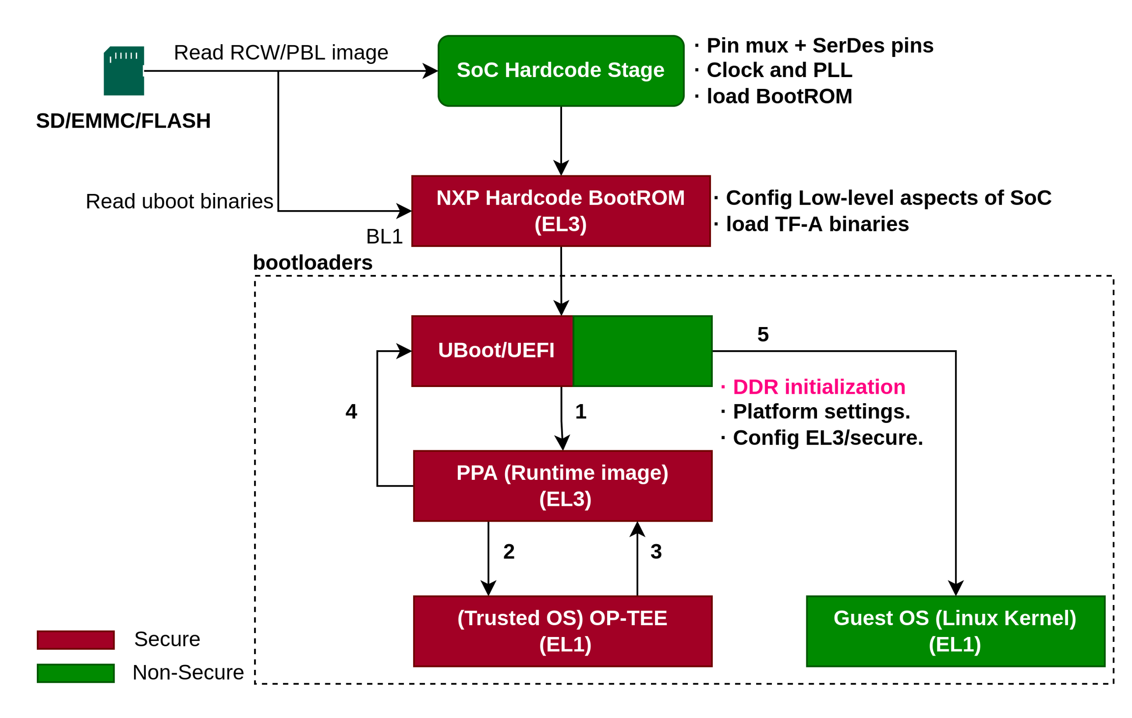
我们可以把boot flow分解为两部分:
SoC阶段(SoC init / BootROM)
Bootloader阶段(uboot)
1.1.2 SoC阶段
SoC阶段分为,SoC init和bootrom阶段。
SoC init
SoC 被释放reset之后,关于boot的主要是,从启动介质(SD/NorFLASH/eMMC)中读取RCW/PBLimage,关于RCW文件可见本小节参引部分。RCW文件主要是对SoC寄存器、外设、DDR的一些配置。SoC通过解析RCW文件,做的工作如下:
pin功能复用初始化;
时钟参数,PLL分频初始化;
加载BootROM。
Note,这部分程序是SoC内部,在流片阶段已经确定,由NXP公司开发集成,不需要做任何修改,需要用户配置的仅仅是RCW文件。
BootROM
SoC init程序把程序控制权hands off给BootROM,开始执行BootROM中的程序,BootROM此时处于ARMv8的异常等级EL3。BootROM需要完成:
配置SoC的一些low-level方面的工作;
加载uboot的image从存储介质中(SD/eMMC/NorFLASH);
跳转uboot
Note,这部分程序是SoC内部,在流片阶段已经确定,由NXP公司开发集成,不需要做任何修改,也无法修改。。
1.1.3 bootloader阶段
bootloader阶段支持两个引导固件,一个是uboot,一个是UEFI。对于NorFLASH存储介质,BootROM无需将其加载到OCRAM(on-chip-ram)上面,支持XIP技术,直接在NorFlash上执行。对于存储在SD/EMMC介质上的程序,需要被BootROM加载到OCRAM上执行。在这个阶段需要bootloader完成:
DDR初始化;
Platform内部的一些设定;
ARMv8 SoC在EL3/secure world中的一些配置。
接着bootloader会从NOR flash或者SD/emmc 加载PPA image。PPA image是一种常驻固件(resident firmware),该固件运行在ARMv8的最高特权等级EL3,为bootloader和操作系统提供一些控制CPU功率,把多核复位的操作。
PPA固件会加载和执行OPTEE,接着会返回PPA固件,PPA固件最后跳回Uboot,切换到非安全模式,来启动内核。
uboot的ppa驱动在: https://github.com/u-boot/u-boot/blob/master/arch/arm/cpu/armv8/fsl-layerscape/ppa.c
1.2 Boot flow with TF-A mode
Trusted Firmware (TF-A) 是一个针对ARMv8-A架构安全世界的实现,是启动secure boot不可或缺的基础组件。TFA提供了trustzone的软件实现。TFA包含5个独立的引导阶段:
Boot stage
Exception level
Description
BL1
EL3
Boot ROM firmware. NOTE:BL1 is embedded in hardware (Boot ROM + PBL commands)
BL2
EL3
Platform initialization firmware
BL31
EL3
Resident runtime firmware
BL32
EL1S
[Optional] Trusted operating system. For example, OP-TEE
BL33
EL2
Normal world bootloader. For example, U-Boot, UEFI
简单的说,TF-A模式的 Boot ROM -> BL2 -> BL31 ->U-boot/UEFI -> Linux,具体如图所示:
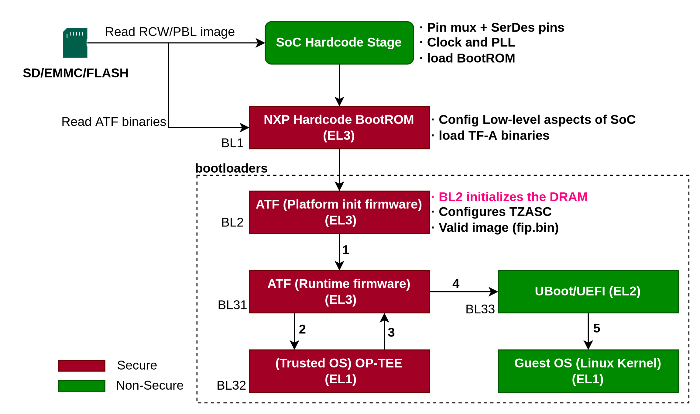
1.2.1 SoC阶段
和Boot flow with PPA mode一致。但是BootROM是加载BL2的二进制文件bl2.bin到OCRAM上。
1.2.2 Bootloader阶段
在BL2阶段主要做:
初始化DRAM,配置TZASC(TrustZone寄存器)
验证BL31/BL32/BL33的images(在
fip.bin中)是否正确,如果正确加载到DDR上。BL2 hands off控制权给BL31(图中 1);
BL31阶段主要:
配置EL31的异常向量表;
配置安全相关的属性(TZPC:TZ保护控制器组件);
提供bootloader和操作系统一些服务,比如控制多核功率和复位管理;
如果使能trusted os,启动trusted os(图中 2),没有则不启动。
BL32阶段主要:
初始化之后,BL32返回BL31(图中 3);
再次回到BL31阶段主要:
控制权交给uboot/uefi,切换异常等级到EL2(图中 4)
再次回到BL31阶段主要:
控制权交给uboot/uefi,切换异常等级到EL2,引导内核启动(图中 5)
注意,ATF模式下,DDR已经被ATF初始化,就无需Uboot对DDR重新进行初始化。从PPA模式转为ATF模式要注意此点。
2. Boot Low-Level Design
因为后续要使能secure boot,因此,只讨论ATF模式的Low Level设计和实验,关于PPA模式不做研究。本节结合flex-builder,讨论bootloader中的一些设计、配置和编译及最终的加载运行。
2.1 ATF
ATF需要注意的问题是:
TF-A的DDR driver的问题;
Flash layout的问题(可能会有);
和uboot配合的问题(可能会有);
2.1.1 ddr driver
在ATF启动模式下,DDR是由ATF进行初始化的,因为ATF需要把fip.bin的image加载到DDR中。这样以来,uboot不需要进行ddr的初始化。Boot ROM -> BL2 (DDR Init) -> BL31 -> U-boot/UEFI -> Linux Kernel。 而ddr的初始化,需要在两个地方改动:
DDR controller
PHY
需要注意TFA的版本问题:
* Platforms
* TFA version
LS1012A, LS1043A, LS1046A, LS1088A, LS2088A
TFA 1.5
LX2160A Rev2, LX2162A
TFA 2.3
DDR Board参数:
* Macro
* File Path
DDRC_NUM_DIMM
Plat/nxp/<SOC>/<Board>/platform_def.h
NUM_OF_DDRC
Plat/nxp/<SOC>/<Board>/platform_def.h
参考: https://docs.nxp.com/bundle/GUID-487B2E69-BB19-42CB-AC38-7EF18C0FE3AE/page/GUID-903DCB6A-FA4B-4A1C-B29D-F75A8CDBA976.html
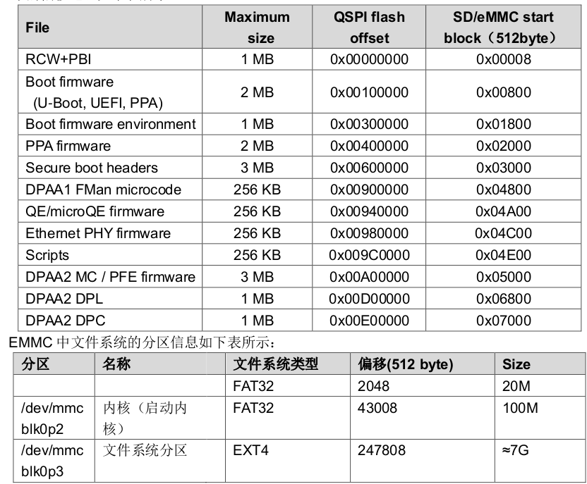
2.1.2 flash layout
这部分需要关注,不同的开发板或设计可能不一致,例如:
PPA引导模式的layout: 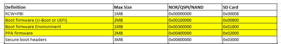
ATF引导模式的layout: 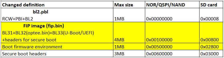
而在飞凌嵌入式的板子中,ATF和PPA模式flash空间已经划分好,各个分区已经共存:
2.1.3 uboot配合
在新版本中不存在这个问题,老版本的LSDK中存在这个问题,需要参考:
https://docs.nxp.com/bundle/GUID-9160E9B1-ADBC-4313-9837-773DA05262FB/page/GUID-FFAB4CBC-D987-474E-ABAA-A7120005FCCC.html
2.1.4 ATF的编译
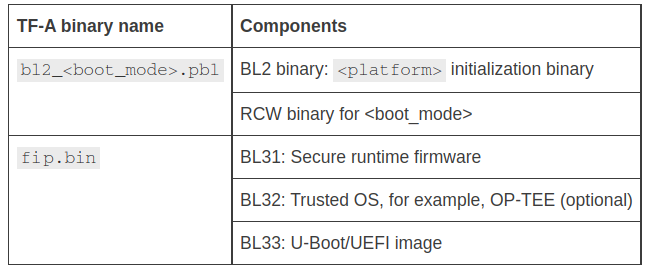
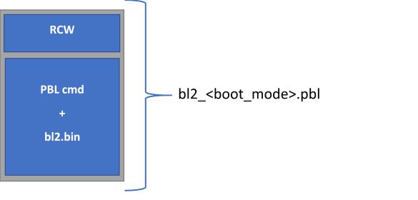
ATF由两部分组成,分别是PBL和fip.bin:
PBL (RCW + PBL_cmd + bl2.bin)
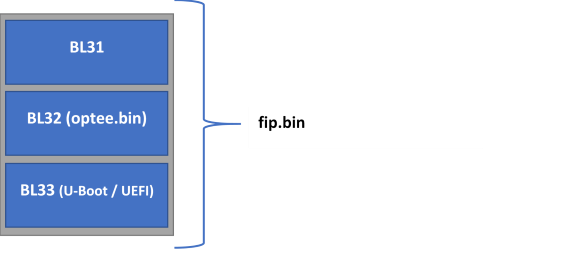
fip.bin ( BL31 + BL32(optee.bin) + BL33(uboot/uefi) )
Note:
<
platform> =ls1012ardb | ls1012afrdm | ls1012afrwy | ls1043ardb | ls1046ardb | ls1088ardb | ls2088ardb | lx2160ardb_rev2 | lx2162aqds<
boot_mode> =nor, nand, sd, emmc, qspi, flexspi_nor
下面的步骤是用来部署TFA的(bl2_<boot_mode>.pbl and fip.bin):
Compile PBL binary from RCW source file
Compile U-Boot binary
[Optional] Compile OP-TEE binary
Compile TF-A binaries (
bl2_<boot_mode>.pblandfip.bin)Program TF-A binaries on specific boot mode
PBL
RCW
编译 rcw_<boot_mode>.bin 二进制文件,这个文件是 bl2_<boot_mode>.pbl 二进制文件所需要的。
$
git clone https://source.codeaurora.org/external/qoriq/qoriq-components/rcw$
cd rcw$
git checkout -b <new branch name> <LSDK tag>. For example, $git checkout -b LSDK-19.03 LSDK-19.03$
cd <platform>If required, make changes to the rcw files.
$
make
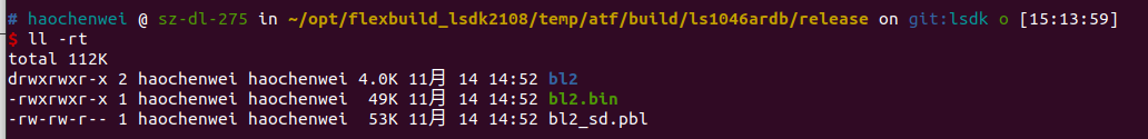
最后会输出文件:
bl2.bin
Clone the atf repository and compile the TF-A binaries, bl2_<boot_mode>.pbl and fip.bin.
$ git clone https://source.codeaurora.org/external/qoriq/qoriq-components/atf$ cd atf$ git checkout -b <new branch name> LSDK-<LSDK version>. For example,$ git checkout -b LSDK-21.08 LSDK-21.08$ export ARCH=arm64$ export CROSS_COMPILE=aarch64-linux-gnu-
编译BL2 binary 带 OPTEE, run this command:
编译bl2需要的 bl2.bin and bl2_<boot_mode>.pbl在aatf/build/<platform>/release/. For any update in the BL2 source code or RCW binary, the bl2_<boot_mode>.pbl binary needs to be recompiled.
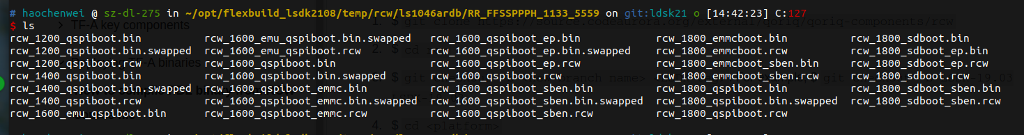
也可以不使用optee.bin生成pbl文件:
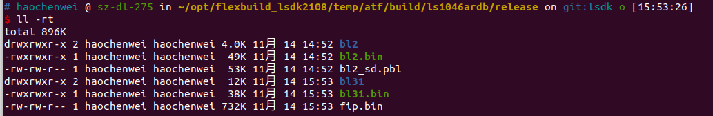
编译的输出文件如图所示:
fip.bin
FIB二进制文件布局如下:
在ATF编译带着OPTEE,命令:
也可以不带OPTEE,命令:
2.1.5 ATF的烧录
ATF可以烧录以QSPI启动模式启动,也可以以SD/EMMC的启动模式启动。
QSPI NOR Flash
进入到uboot,的使用tftp加载数据,然后写入到NOR Flash
Boot from QSPI NOR flash0
Program QSPI NOR flash1: =>
sf probe 0:1Flash bl2_qspi.pbl:
Flash fip.bin:
Flash DDR FIP binary (Supported only for LX2162AQDS or LX2160ARDB Rev2):
Boot from QSPI NOR flash1. The board will boot with TF-A
SD/eMMC Card
Boot from QSPI NOR flash0.
Flash bl2_sd.pbl on SD/eMMC card:
Here, blk_cnt refers to number of blocks in SD card that need to be written as per the file size. For example, when you load bl2_sd.pbl from the TFTP server, if the bytes transferred is 82809 (14379 hex), then blk_cnt is calculated as 82809/512 = 161 (A1 hex). For this example, mmc write command will be:
=> mmc write 82000000 8 A1.Flash fip.bin on SD/eMMC card
Here, blk_cnt refers to number of blocks in SD card that need to be written as per the file size. For example, when you load fip.bin from the TFTP server, if the bytes transferred is 1077157 (106fa5 hex) , then blk_cnt is calculated as1077157/512 = 2103 (837 hex) . For this example, mmc write command will be:
=> mmc write 82000000 800 837.Flash DDR FIP binary (Supported only for LX2162AQDS or LX2160ARDB Rev2):
Here, blk_cnt refers to number of blocks in SD card that need to be written as per the file size.
Boot from SD card. The board will boot with TF-A.
2.2 U-Boot
2.2.1 需要在uboot上做的调整
在TF-A的启动流程,DDR不需要再被uboot初始化,而是被ATF进行初始化,DDR的初始化程序可以被加入到
<atf_dir>/plat/nxp/soc-<soc-name>/<soc-name>ardb/ddr_init.c。DDR驱动可以被找到在<atf_dir>/plat/nxp/drivers/ddr任何内部状态的初始化都可以加入到
soc.c在<atf_dir>/plat/nxp/soc-<soc-name>/defconfig文件,格式应该是:
<platform>_tfa_defconfig. For example, for LX1046ARDB Rev2, defconfig needs to be used islx1046ardb_tfa_defconfigTF-A的defconfig被创建主要修改:
PPA模式 disable
启动环境支持 sd boot或者Flex SPI
一些其他的改变:
Boot command改变支持autoboot:
XSPI_NOR_BOOTCOMMAND
SD_BOOTCOMMAND
MC init命令改变:
XSPI_MC_INIT_CMD
SD_MC_INIT_CMD
2.2.2 编译uboot
boot.bin文件被fip.bin所依赖:
$ git clone https://source.codeaurora.org/external/qoriq/qoriq-components/u-boot.git$ cd u-boot$ git checkout -b <new branch name> LSDK-<LSDK version>. For example,$ git checkout -b LSDK-21.08 LSDK-21.08$ export ARCH=arm64$ export CROSS_COMPILE=aarch64-linux-gnu-$ make distclean$ make <platform>_tfa_defconfig$ make
2.2.3 编译secure uboot
和上面的区别在于,$ make <platform>_tfa_defconfig 和 $ make <platform>_tfa_SECURE_BOOT_defconfig 配置文件不同。
You need to compile the u-boot.bin binary to build the fip.bin binary. Clone the u-boot repository and compile the U-Boot binary for TF-A.
$ git clone https://source.codeaurora.org/external/qoriq/qoriq-components/u-boot.git$ cd u-boot$ git checkout -b <new branch name> <tag>. For example,$ git checkout -b LSDK-21.08 LSDK-21.08$ export ARCH=arm64$ export CROSS_COMPILE=aarch64-linux-gnu-$ make distclean$ make <platform>_tfa_SECURE_BOOT_defconfig$ make
NOTE:If the make command shows the error "*** Your GCC is older than 6.0 and is not supported", ensure that you are using Ubuntu 18.04 64-bit version for building 21.08 U-Boot binary.
The compiled secure U-Boot image, u-boot.bin-tfa-secure-boot, is available at u-boot/.
2.3 UEFI
Ref
最后更新于