需要在硬件设计上引出该引脚,为Provisioning做准备。
#### Byte swap for reading and writing SRKH/OTPMK
应谨慎编写SRKH和OTPMK。如果使用Core写入SRKH和OTPMK,则需要交换SRKH与OTPMK。但是,如果使用DAP或SFP写入SRKH和OTPMK,则不需要交换。有关详细信息,请参阅下表。
参考:
#### Program OTPMK
After [enabling POVDD](https://docs.nxp.com/bundle/GUID-3FFCCD77-5220-414D-8664-09E6FB1B02C6/page/GUID-0EFF85FB-9070-4D76-A926-B973CA6C8FB5.html#GUID-0EFF85FB-9070-4D76-A926-B973CA6C8FB5), follow these steps to program OTPMK at U-Boot:
参考:
#### Program SRKH mirror registers
参考:
#### Write SFP\_INGR register
参考:
### 5.3 build secure boot image
#### 5.3.1 using flexbuild
After setting up the flexbuild environment, run the following commands to generate images for NXP CoT:
```
$ flex-builder -i clean-firmware
$ flex-builder -i mkfw -m -b -T nxp-cot (optional)
$ flex-builder -i mkfw -m -b -s ('-s' is equivalent to '-T nxp-cot')
```
For example:
```
$ flex-builder -i clean-firmware
$ flex-builder -i mkfw -m lx2162aqds -b xspi -T nxp-cot (optional)
$ flex-builder -i mkfw -m ls1046ardb -b xspi -s ('-s' is equivalent to '-T nxp-cot')
```
The images will be available at: `/build/images/`.
#### 5.3.2 using manually TF-A
需要在TF-A中设定:
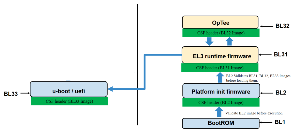
* * Set `TRUSTED_BOARD_BOOT=1` to enable trusted board boot. NXP CoT is enabled automatically when `TRUSTED_BOARD_BOOT=1` and `MBEDTLS_DIR path` is not specified.
* Specify path of the CST repository as `CST_DIR` to generate CSF headers. In NXP CoT, CSF header is embedded to the BL31, BL32, and BL33 images.
* Default input files for CSF header generation are available in `CST_DIR`.
* As per the default input file, you need to generate following RSA key pairs and add them to the ATF repository:
* srk.pri
* srk.pub
* The RSA key pairs can be generated using the gen\_keys CST tool. To change the input file, you can use the options `BL33_INPUT_FILE`, `BL32_INPUT_FILE`, `BL31_INPUT_FILE`.
注意:TRUSTED\_BOARD\_BOOT 也可以被使能在非安全启动。 然而,ROTPK在非安全启动流中被忽略,并且故障不会导致SNVS转换。
```
make PLAT= TRUSTED_BOARD_BOOT=1 CST_DIR=$CST_DIR_PATH \
RCW=$RCW_BIN \
BL32=$TEE_BIN SPD=opteed\
BL33=$UBOOT_SECURE_BIN \
pbl \
fip
```
To prepend CSF headers to BL31, BL32, and BL33 images:
```
make PLAT= all fip pbl SPD=opteed BL32=tee.bin BL33=u-boot.bin \
RCW = \
TRUSTED_BOARD_BOOT=1 CST_DIR= BL33_INPUT_FILE= BL32_INPUT_FILE= \
BL31_INPUT_FILE =
```
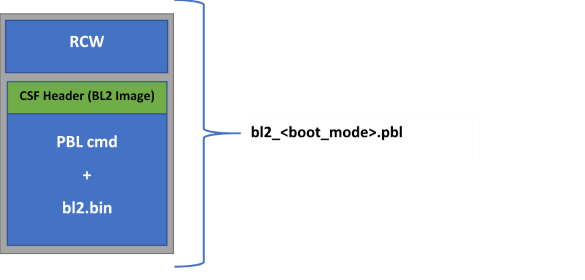
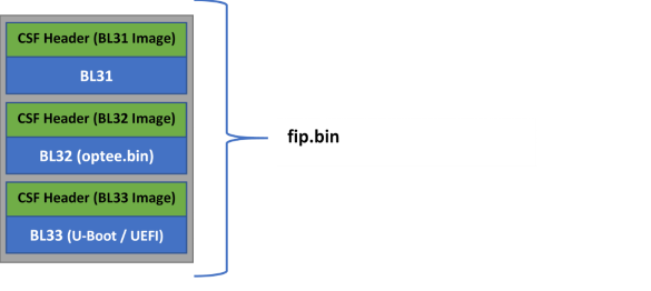
The secure boot binaries for NXP CoT are available in the `atf` directory:
* `build//release/fip.bin`
* `build//release/bl2_flexspi_nor_sec.pbl`
## 6. Provisioning
NXP的Trust Architecture (TA),提供片上FuSE(OTP)。通过Security Fuse Processor (SFP)来配置以下寄存器:
* One Time Programmable Master Key Registers (OTPMKRs)
* Super Root Key Hash Registers (SRKHRs)
* Debug Challenge and Response Value Registers (DCVRs and DRVRs)
* OEM Security Policy Registers (OSPRs)
* OEM Unique ID/Scratch Pad Registers (OUIDRs)
### 6.1 FuSe Programming Scenarios
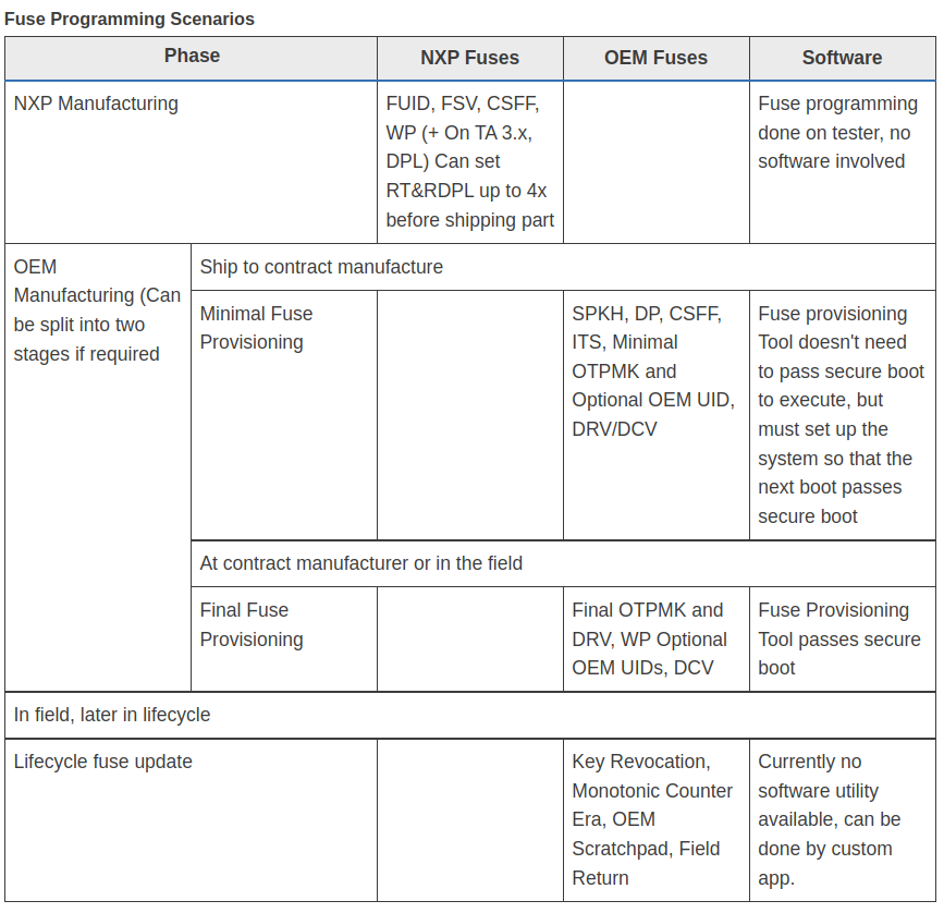
### 6.2 Fuse Provisioning during OEM Manufacturing
这一步被分为两个阶段:
* Stage 1: (Non-secure boot) – Minimal Fuse Provisioning
* Stage 2: (Secure Boot) – Final Fuse Provisioning
#### stage 1
如果启动secureboot 最小的配置项需要兼顾如下:
* SRKH
* CSFF
* Minimal OTPMK
此阶段不通过安全引导来执行,但必须设置FuSe,以便下一次引导通过安全引导。如果这一步骤发生在可信的环境中,**OEM**可以选择在这一阶段自行编写所有保险丝。
#### stage 2
剩下的FuSe可以在secure boot启动的时候进行编写。注意,此步骤导致OEM阶段FuSe熔断,FuSe不再可写。
### 6.3 Fuse Provisioning Utility
NXP的安全固件中包含了做Provisioning的固件,这个固件编译可以参考下面 build fuse provisioning firmware image一节。
关于fuses值的信息将通过fuses文件提供。fuses文件是一个二进制文件,具有指示fuses及其相应值的位。CST提供了一个输入文件,用户可以在其中输入所需的值。该工具生成一个fuses文件,该文件在BL2映像中解析以进行fuses配置。安全固件将进行必要的检查,以确定所提供的输入值是否正确。例如,当SFP保险丝中已设置OEM\_WP时,无法对OTPMK、SRKH进行编程。
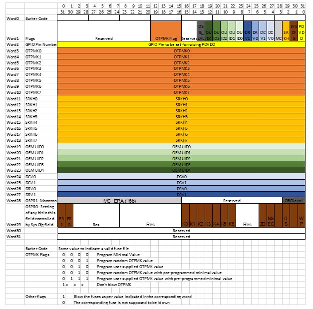
#### fuse file structure
#### 配置文件示例
```
---------------------------------------------------
# Specify the platform. [Mandatory]
# Choose Platform - LS1/LS1043/LS1012/LS1046
PLATFORM=LS1046
---------------------------------------------------
# GPIO Pin to be set for raising POVDD [Optional]
POVDD_GPIO=
---------------------------------------------------
# One time programmable master key flags in binary form.[Mandatory]
# 0000 -> Program default minimal OTPMK value
# 0001 -> Program random OTPMK value
# 0010 -> Program user supplied OTPMK value
# 0101 -> Program random OTPMK value with pre-programmed minimal value
# 0110 -> Program user supplied OTPMK value with pre-programmed minimal value
# 1xxx -> Don't blow OTPMK
OTPMK_FLAGS=0000
# One time programmable master key value.
# [Optional dependent on flags, Mandatory in case OTPMK_FLAGS="0010" or "0110"]
OTPMK_0=
OTPMK_1=
OTPMK_2=
OTPMK_3=
OTPMK_4=
OTPMK_5=
OTPMK_6=
OTPMK_7=
---------------------------------------------------
# Super root key hash [Optional]
SRKH_0=
SRKH_1=
SRKH_2=
SRKH_3=
SRKH_4=
SRKH_5=
SRKH_6=
SRKH_7=
---------------------------------------------------
# Specify OEM UIDs. [Optional]
# e.g OEM_UID_0=11111111
OEM_UID_0=
OEM_UID_1=
OEM_UID_2=
OEM_UID_3=
OEM_UID_4=
---------------------------------------------------
# Specify Debug challenge and response values. [Optional]
# e.g DCV_0=11111111
DCV_0=
DCV_1=
DRV_0=
DRV_1=
---------------------------------------------------
# Specify Debug Level in binary form. [Optional]
# 000 -> Wide open: Debug portals are enabled unconditionally.
# 001 -> Conditionally open via challenge response, without notification.
# 01x -> Conditionally open via challenge response, with notification.
# 1xx -> Closed. All debug portals are disabled.
DBG_LVL=
---------------------------------------------------
# System Configuration register bits in binary form [Optional]
# WP (OEM write protect)
# ITS (Intent to Secure)
# NSEC (Non secure)
# ZD (ZUC Disable)
# K0,K1,K2 (Key revocation bits)
# FR0 (Field return 0)
# FR1 (Field return 1)
WP=
ITS=
NSEC=
ZD=
K0=
K1=
K2=
FR0=
FR1=
---------------------------------------------------
# Specify the output fuse provisioning file name. (Default:fuse_scr.bin) [Optional]
OUTPUT_FUSE_FILENAME=fuse_scr.bin
---------------------------------------------------
```
### 6.4 Deploy and run fuse provisioning
分为以下步骤:
* 开启POVDD
* 编译Provisioning firmware image
* 部署image到板子上
* 执行Provisioning
**开启POVDD**
检查`PWR_PROG_SFP`引脚,高电平有效。
**编译Provisioning firmware image**
1. 编译CST `$ flex-builder -c cst`
2. 编译Provisioning firmware(在编译firmware之前需要配置):
1. Set `CONFIG_FUSE_PROVISIONING=y` in file `flexbuild_/configs/sdk.yml`
3. \[可选] 编辑用于Provisioning的输入文件:
1. The input file is available at: `/components/apps/security/cst/input_files/gen_fusescr//input_fuse_file`,注意`` 可以是 `ls2088_1088` or `ls104x_1012`
4. 生成image:
```
$ flex-builder -i mkfw -m -b
```
1. `` can be ls1012ardb, ls1012afrwy, ls1021atwr, ls1028ardb, ls1043ardb, ls1046ardb, ls1046afrwy, ls1088ardb\_pb, ls2088ardb, lx2162aqds
2. `` can be nor, sd, emmc, qspi, xspi, nand
5. 最后生成新的img位于:`flexbuild_/build/images/firmware__boot.img`
**Deploy and run fuse provisioning firmware image on board**
通过uboot烧写 `firmware_ls1046ardb_sdboot.img` ,可以把 `firmware_ls1046ardb_sdboot.img` 放在sd卡中,使用uboot来把这个img烧写到mmc中。
```
=> tftp a0000000 firmware_ls1046ardb_sdboot.img => mmc write a0000000 8 1fff8 => cpld reset sd
```
也可以通过手动烧写
**Validate fuse provisioning**
启动uboot之后,进入uboot操作界面。检查DCFG scratch 4寄存器是否存在错误代码。例如,对LS1046ARDB运行以下命令以检查错误代码:
```
=> md 1ee020c 1
```
如果md命令未显示任何错误,则Provisioning成功。
```
01ee020c: 00000000
```
Error code可以参考:
## 7. U-Boot Secure feature
### 7.1 一些在uboot环境中的命令
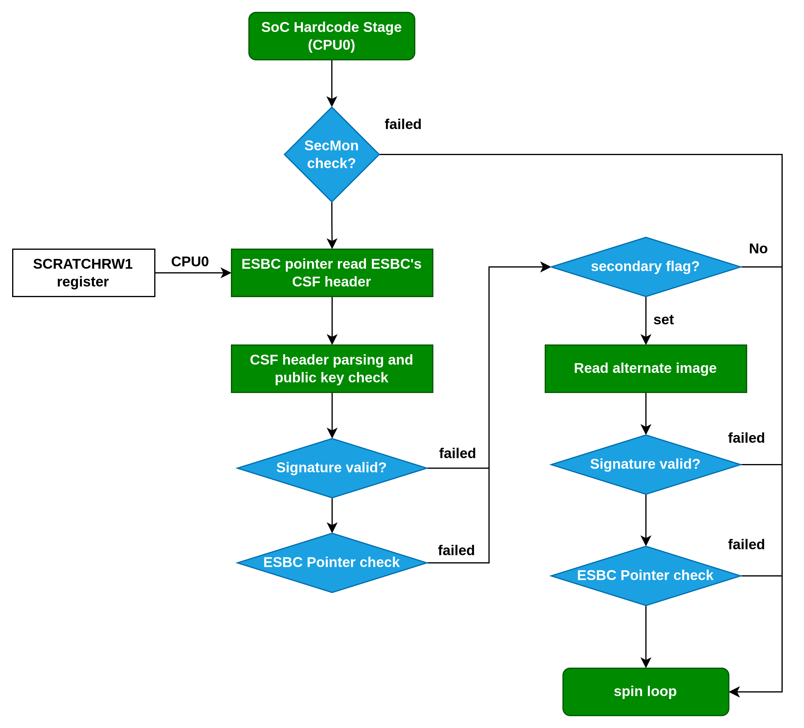
为了建立安全启动信任链,一些 U-Boot 命令已添加到 ESBC 代码中。
**esbc\_validate command**
验证CSF header的命令。
`esbc_validate []`
| 参数 | 解释 |
| -------------- | -------------------------------------- |
| img\_hdr | image的CSF header位置 |
| pub\_key\_hash | 用于验证image的公钥hash。可选,如果不提供则使用ISBC一样的key |
**esbc\_halt command**
```
esbc_halt (no arguments)
```
可以让处理器进入spin loop状态。
**blob enc command**
此命令将创建放置在 src 位置的image加密成blob形式,并将该 blob 放置在 dst 位置。
```
blob enc
```
| 参数 | 解释 |
| --------------------- | -------------------------------- |
| src location | 需要加密的image地址 |
| dst location | blob输出的地址 |
| length | 需要加密的image的长度 |
| key\_modifier address | 放置一个 16 字节长的随机数(key modifier)的地址 |
**blob dec command**
此命令将解密放置在 src 位置的 blob的解密结果放置在 dst 位置。
```
blob enc
```
| 参数 | 解释 |
| --------------------- | -------------------------------- |
| src location | 需要解密的blob地址 |
| dst location | 解密后的image输出的地址 |
| length | 需要解密的image的长度 |
| key\_modifier address | 放置一个 16 字节长的随机数(key modifier)的地址 |
### 7.2 Bootscript
Bootscript是uboot image的一个执行脚本,内部包含了执行uboot的命令。ESBC在除了验证uboot之外,还会在验证执行uboot之前验证bootscript。bootscript有一些规则需要遵守:
* Bootscript 可以包含 U-Boot 支持的任何命令。而secure boot不对脚本内调用的命令是否正确进行验证,换句话说,secure boot假设script上所有的命令都是正确的。
* 如果bootscript中出现了一些语法错误,会导致boot进入spin loop状态;
* 在uboot脚本中使用验证命令,不支持分散的images;
* 如果ITS fuse被熔断,任何在验证image的时候的错误都会导致系统reset。因此查找错误应该在这次启动之前的log中寻找 。
ESBC的U-Boot 期望从flash加载引导脚本。 ESBC的U-Boot 代码假定用于签署引导脚本的公钥/私钥对与签署 U-Boot 映像时使用的公钥/私钥对相同。 如果用户使用不同的密钥对对镜像进行签名,则密钥对的 N 和 E 分量的哈希应在宏中定义:
```
CONFIG_BOOTSCRIPT_KEY_HASH
```
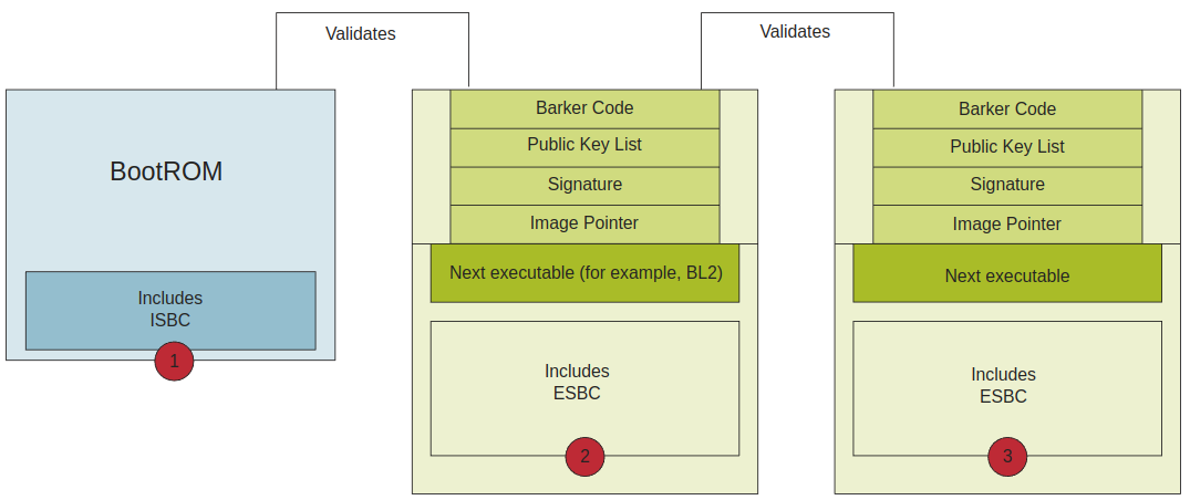
#### 7.2.1 Chain of Trust
Bootscript 包含有关下一级image的信息,例如 MC,Linux ESBC 根据它们的公钥验证这些image。 如果需要,MC 使用经过验证的 MC 映像启动,最后执行 bootm 命令以将控制权传递给 Linux 映像。
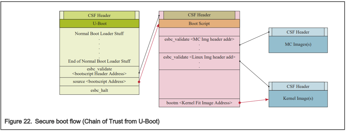
上面图片的bootscript示例:
```bash
# Get Images and Headers on DDR
.
.
.
# Validate the Images. ( is optional)
esbc_validate
esbc_validate
.
.
.
# Boot the Linux
bootm
```
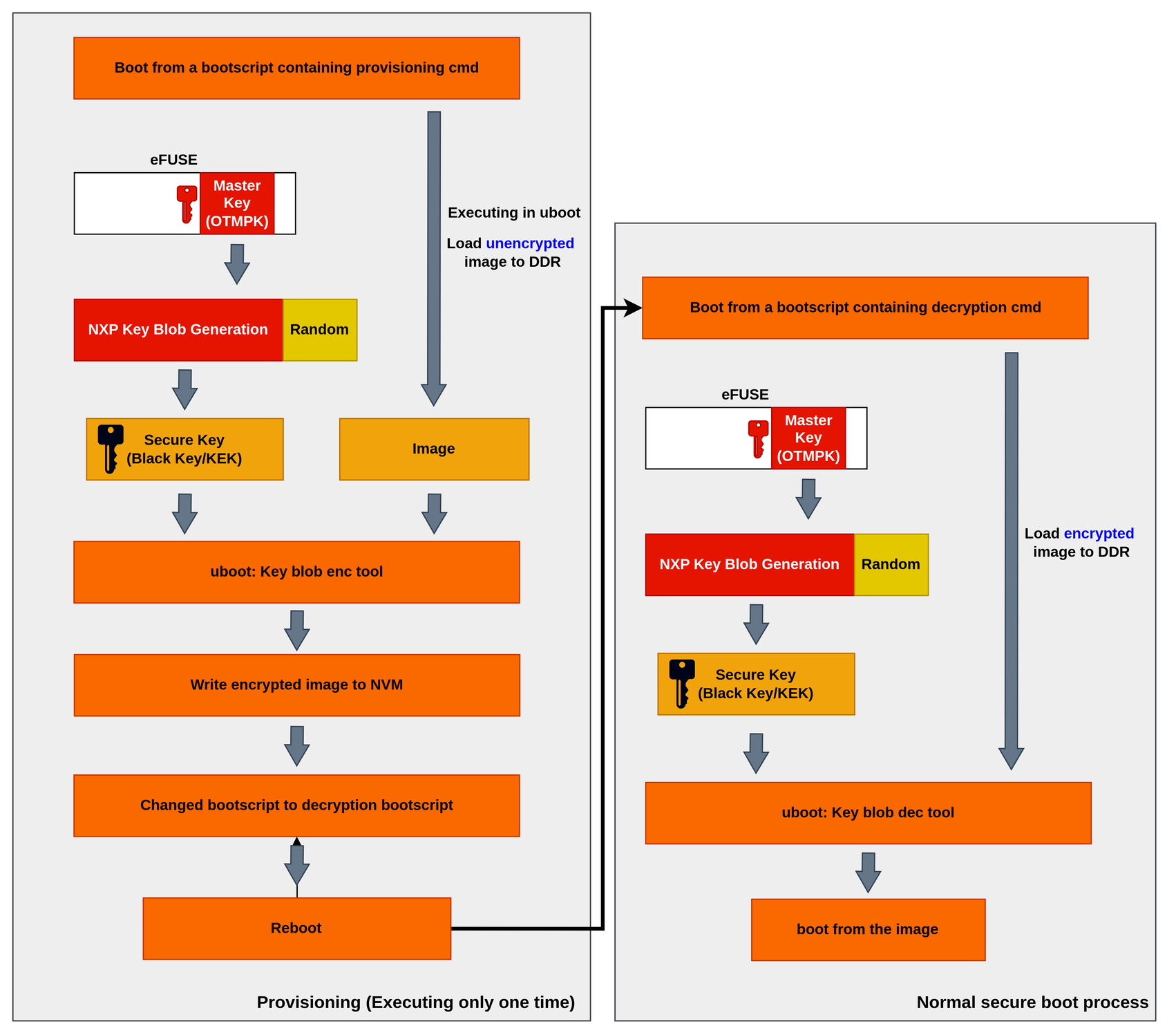
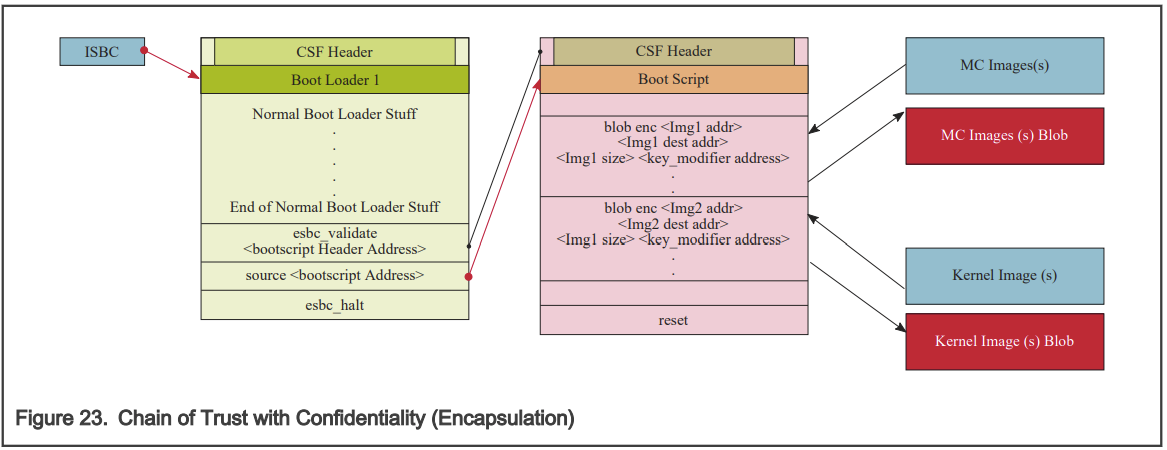
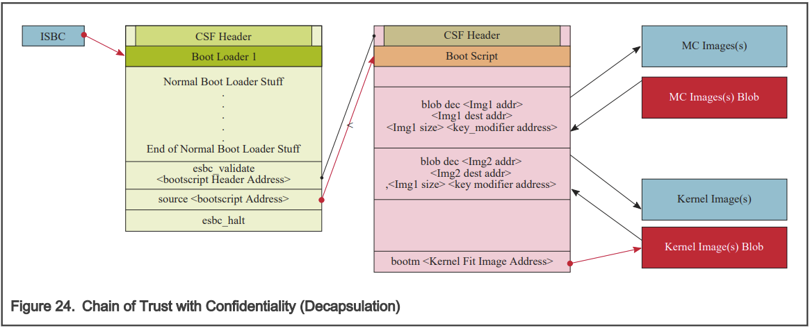
#### 7.2.2 Chain of Trust with confidentiality
为了建立具有机密性的信任链,可以使用加密的 blob 机制。 在这个信任链中,经过验证的image被允许使用一次性可编程主密钥(One Time Programmable Master Key)来解密系统image信息。 将使用两个引导脚本。 首先使用封装引导脚本创建下一级image(例如 MC、Linux)的 blob 并将它们保存在闪存上。 在此之后,在将封装引导脚本替换为解封装引导脚本后启动系统,解封装 blob 并启动 MC 和 Linux。
**加密**
```bash
# Get Images on DDR
.
.
.
# Create the Blobs
blob enc
blob enc
blob enc
.
.
.
Save The Blobs created on Flash
.
.
.
# End of Encap Boot Script (This is one time only and must be replaced with decap Boot Script)
```
**解密**
```bash
# Get Images Blobs on DDR
.
.
.
# Decap the Blobs to get the actual images
blob dec
blob dec
blob dec
.
.
.
# Boot the Linux
bootm
```
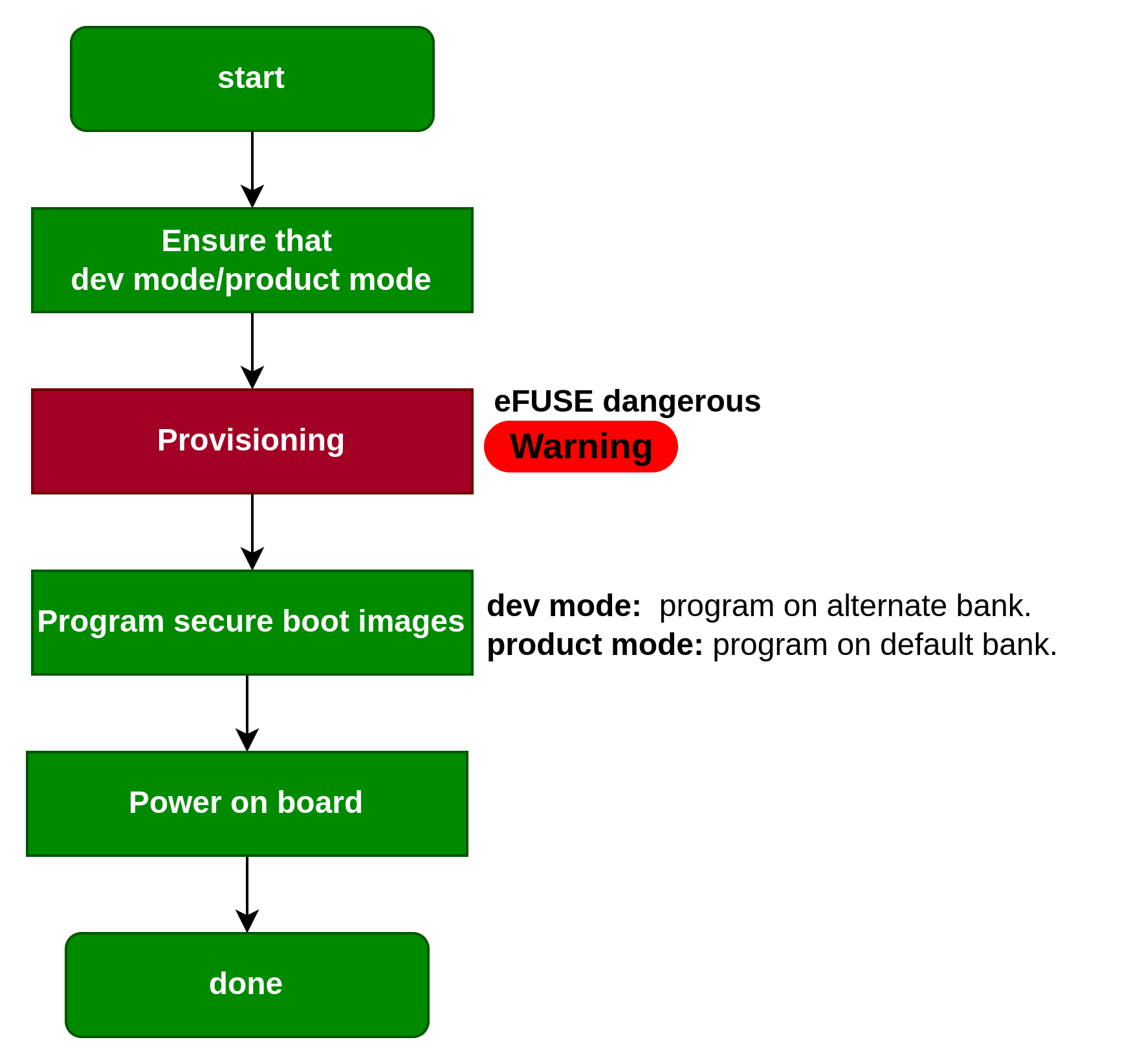
## 8. Secure Boot Overview
This section describes the steps to run secure boot on NXP Layerscape family SOC-based boards:
**The procedure to run the secure boot is shown in the following steps:**
1. Prepare board for secure boot
1. [Enable POVDD](https://docs.nxp.com/bundle/GUID-487B2E69-BB19-42CB-AC38-7EF18C0FE3AE/page/GUID-0EFF85FB-9070-4D76-A926-B973CA6C8FB5.html#GUID-0EFF85FB-9070-4D76-A926-B973CA6C8FB5)
2. [Program OTPMK](https://docs.nxp.com/bundle/GUID-487B2E69-BB19-42CB-AC38-7EF18C0FE3AE/page/GUID-F780D1D5-F1B2-478B-86AE-267D74F9C790.html#GUID-F780D1D5-F1B2-478B-86AE-267D74F9C790)
3. [Program SRK](https://docs.nxp.com/bundle/GUID-487B2E69-BB19-42CB-AC38-7EF18C0FE3AE/page/GUID-D8CC0ABA-108D-4966-8C01-F584B897B9E2.html#GUID-D8CC0ABA-108D-4966-8C01-F584B897B9E2)
2. Build secure boot images for NXP CoT and Arm CoT
* [using flex-builder](https://docs.nxp.com/bundle/GUID-487B2E69-BB19-42CB-AC38-7EF18C0FE3AE/page/GUID-2AE4E770-FCC5-4376-93CE-D69F3A3BF9DF.html#GUID-2AE4E770-FCC5-4376-93CE-D69F3A3BF9DF), or
* [manually (using TF-A)](https://docs.nxp.com/bundle/GUID-487B2E69-BB19-42CB-AC38-7EF18C0FE3AE/page/GUID-07074F71-3F5C-484B-9965-93D919936CB0.html#GUID-07074F71-3F5C-484B-9965-93D919936CB0)
3. [Program secure boot images for NXP CoT and Arm CoT](https://docs.nxp.com/bundle/GUID-487B2E69-BB19-42CB-AC38-7EF18C0FE3AE/page/GUID-11BC1A68-D413-4105-9469-0020BAAE1E23.html#GUID-11BC1A68-D413-4105-9469-0020BAAE1E23)
4. [Steps to run chain of trust with confidentiality](https://docs.nxp.com/bundle/GUID-487B2E69-BB19-42CB-AC38-7EF18C0FE3AE/page/GUID-7EE8D47D-42C5-4D37-A94B-A75A73148A30.html#GUID-7EE8D47D-42C5-4D37-A94B-A75A73148A30)
Note, **Red** blocks are dangerous, and can't take it back.
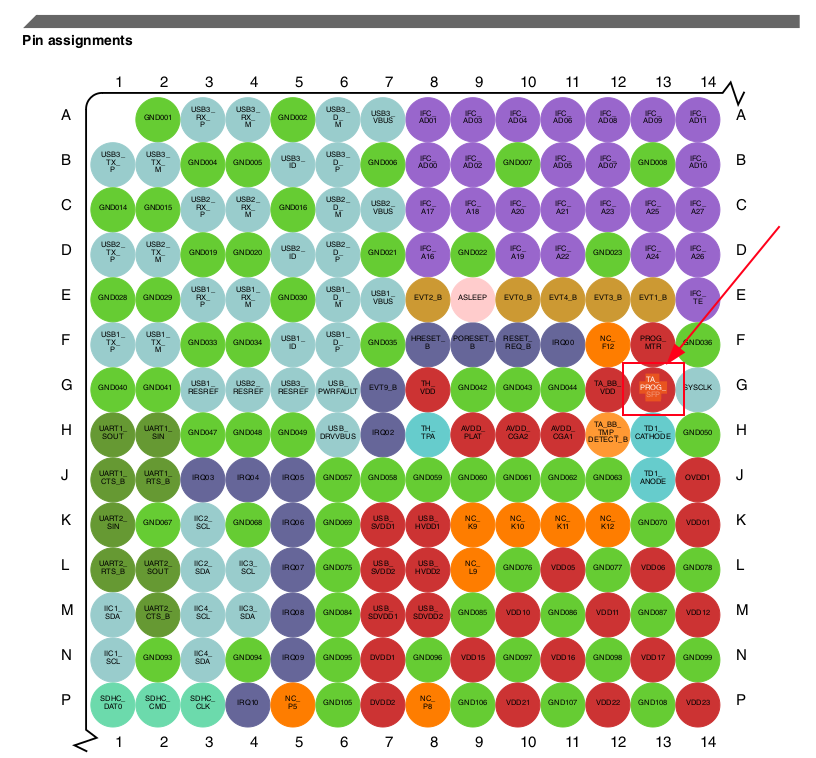
## 9. Enabling Secure Boot
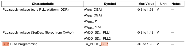
### 9.1 Enable POVDD
The use of the trust architecture feature is dependent on programming fuses in the Security Fuse Processor (SFP). To program SFP fuses, the user is required to **supply 1.8 V to the TA\_PROG\_SFP pin** Power sequencing. TA\_PROG\_SFP should only be powered for the duration of the fuse programming cycle, with a per-device limit of six fuse programming cycles. At all other times, TA\_PROG\_SFP should be connected to GND. The TA\_PROG\_SFP pin is shown in the following figure:
This figure shows the TA\_PROG\_SFP timing diagram:
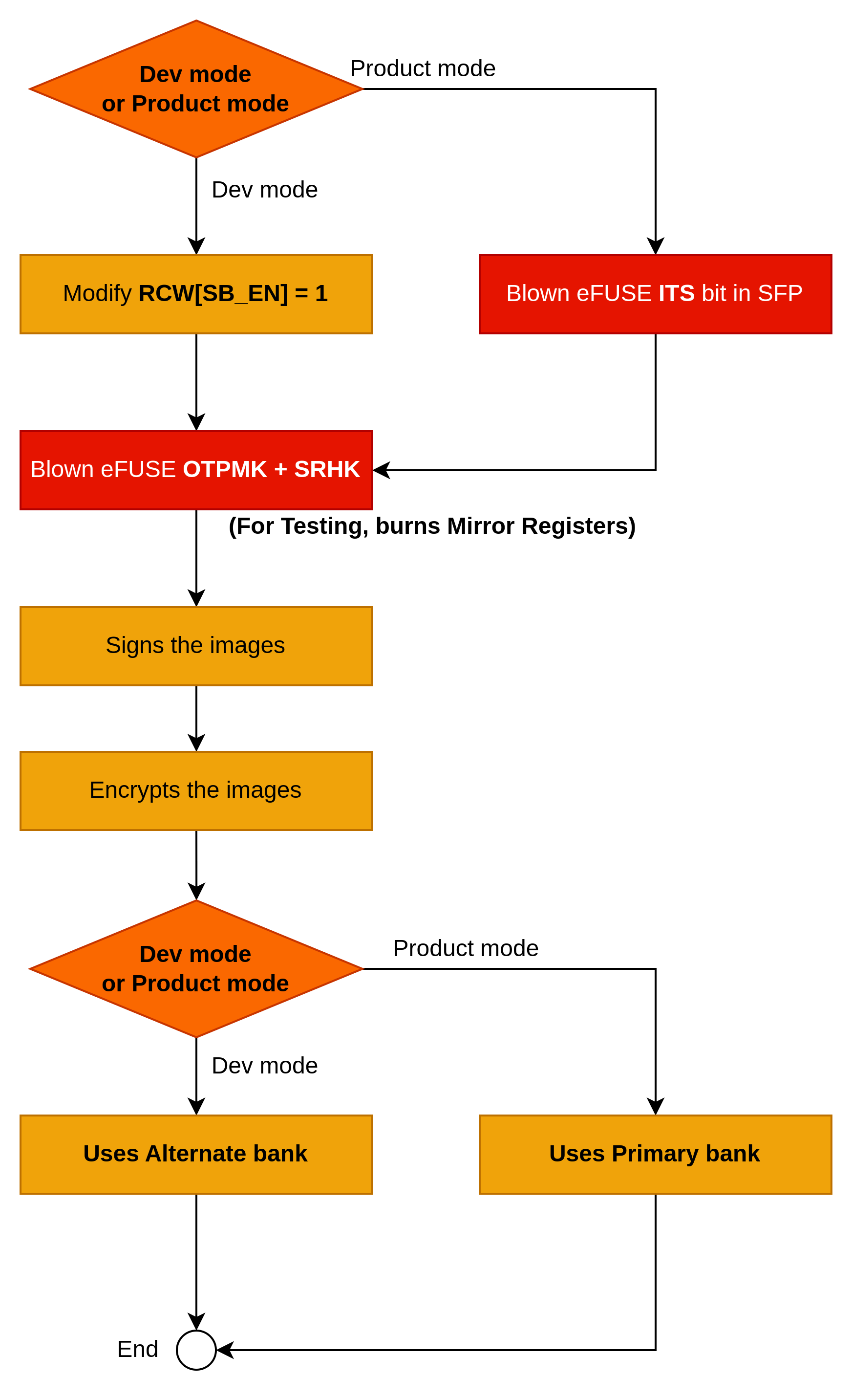
### 9.2 RCW modifying
The reset configuration word (RCW) resides in non-volatile memories (for example, NOR, QSPI, SDHC). It gives the flexibility to accommodate a large number of configuration parameters to support a high degree of configurability of the SoC. Configuration parameters generally include:
* Frequencies of various blocks including cores/DDR/interconnect.
* IP pin-muxing configurations
* Other SoC configurations
The RCW's provided with the release enable the following features:
* Boot location as NOR flash
* Enables 4 UART without flow control
* Enables I2C1, I2C2, I2C3, I2C4, SDHC, IFC, PCIe, SATA
#### How to change RCW?
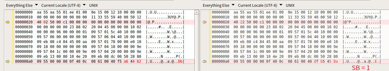
RCW\[SB\_EN] = 1 can be set by the following figure:
Build the new RCW file:
`$ flex-builder -i clean-firmware`
`$ flex-builder -c firmware -a arm64 -m ls1046ardb -b sd -S 1040`
#### Cat RCW file
In the [LS1046A Reference Manual](https://www.nxp.com/webapp/Download?colCode=LS1046ARM) - 4.4.6.1 RCW Field Definitions, the offset of the `SB_EN` is 202 (0xCA) bits.
The position of the SB\_EN is fixed in the following figure:
### 9.3 Blown eFUSE
#### 9.3.1 Provisioning Ordering
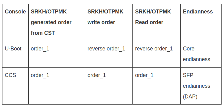
**SRKH and OTPMK should be carefully written keeping in mind the SFP Block Endianness. If SRKH and OTPMK are written using Core, SRKH and OTPMK need to be swapped. However, if SRKH and OTPMK are written using DAP or SFP, swap is not required. Refer the following table for details.**
| **Console** | **SRKH/OTPMK generated order from CST** | **SRKH/OTPMK write order** | **SRKH/OTPMK Read order** | **Endianness** |
| ----------- | --------------------------------------- | -------------------------- | ------------------------- | -------------------- |
| U-Boot | order\_1 | **reverse order\_1** | **reverse order\_1** | Core endianness |
| CCS | order\_1 | order\_1 | order\_1 | SFP endianness (DAP) |
**Assuming following SRKH values are generated:**
```
SRK (Public Key) Hash:
fdc2fed4317f569e1828425ce87b5cfd34beab8fdf792a702dff85e132a29687
SFP SRKHR0 = fdc2fed4
SFP SRKHR1 = 317f569e
SFP SRKHR2 = 1828425c
SFP SRKHR3 = e87b5cfd
SFP SRKHR4 = 34beab8f
SFP SRKHR5 = df792a70
SFP SRKHR6 = 2dff85e1
SFP SRKHR7 = 32a29687
```
**Execute the following commands at the CCS console to permanently write SRKH using DAP/SFP:**
```
ccs::write_mem 32 0x1e80254 4 0 0xfdc2fed4
ccs::write_mem 32 0x1e80258 4 0 0x317f569e
ccs::write_mem 32 0x1e8025c 4 0 0x1828425c
ccs::write_mem 32 0x1e80260 4 0 0xe87b5cfd
ccs::write_mem 32 0x1e80264 4 0 0x34beab8f
ccs::write_mem 32 0x1e80268 4 0 0xdf792a70
ccs::write_mem 32 0x1e8026c 4 0 0x2dff85e1
ccs::write_mem 32 0x1e80270 4 0 0x32a29687
```
**Execute the following commands at the U-Boot console to permanently write SRKH using core:**
```
mw.l 0x1e80254 0xd4fec2fd
mw.l 0x1e80258 0x9e567f31
mw.l 0x1e8025c 0x5c422818
mw.l 0x1e80260 0xfd5c7be8
mw.l 0x1e80264 0x8fabbe34
mw.l 0x1e80268 0x702a79df
mw.l 0x1e8026c 0xe185ff2d
mw.l 0x1e80270 0x8796a232
mw.l 0x1e80020 0x2
```
#### 9.3.2 Program OTPMK
After [enabling POVDD](https://docs.nxp.com/bundle/GUID-487B2E69-BB19-42CB-AC38-7EF18C0FE3AE/page/GUID-0EFF85FB-9070-4D76-A926-B973CA6C8FB5.html#GUID-0EFF85FB-9070-4D76-A926-B973CA6C8FB5), follow these steps to program OTPMK at **U-Boot**:
**Verify**
Verify the SNVS register - HPSR to check whether OTPMK is fused already.
```
=> md $SNVS_HPSR_REG
88000900
```
OTPMK\_ZERO\_BIT (second nibble) is 1, indicating that OTPMK is not fused. The second nibble of 8**8**000900 is 1 indicatesthe OTPMK is not fused.
**Gen OTPMK**
Generate OTPMK by CST `./gen_otpmk_drbg -b 2`
**Fuse OTPMK**
**Note, write order !!!**
```
=> mw.l $OTPMKR0 0x125ce2c7
=> mw.l $OTPMKR1 0xdf730728
=> mw.l $OTPMKR2 0x5ef92af6
=> mw.l $OTPMKR3 0xf6dafed7
=> mw.l $OTPMKR4 ...
=> mw.l $OTPMKR5 ...
=> mw.l $OTPMKR6 ...
=> mw.l $OTPMKR7 ...
```
**Check OTPMK**
At the U-Boot prompt, verify that the **SNVS registers** for OTPMK are correctly written.
Check if OPTMK is fused.
```
=> md $SNVS_HPSR_REG
80000900
```
OTPMK\_ZERO\_BIT (second nibble) is 0, indicating that OTPMK is fused.
Read OTPMK:
```
=> md $OTPMKR0 0x10
01e80234: ffffffff ffffffff ffffffff ffffffff ................
01e80244: ffffffff ffffffff ffffffff ffffffff ................
```
**Note:** OTPMK is not visible in plain.
#### 9.3.3 Program SRKH mirror registers
After [enabling POVDD](https://docs.nxp.com/bundle/GUID-487B2E69-BB19-42CB-AC38-7EF18C0FE3AE/page/GUID-0EFF85FB-9070-4D76-A926-B973CA6C8FB5.html#GUID-0EFF85FB-9070-4D76-A926-B973CA6C8FB5), follow these steps to program SRKH registers at U-Boot:
**verify**
Check if SRKH is fused.
```
=> md $SRKHR0 0x10
01e80254: 00000000 00000000 00000000 00000000 ................
01e80264: 00000000 00000000 00000000 00000000 ................
```
Zero indicates that SRKH is not fused.
**Fuse SRKH**
The CST tool will generate the SRK by inputting public key.
**SRKH should be carefully written considering the SFP block endianness.**
```
=> mw.l $SRKHR0 0x82d05d68
=> mw.l $SRKHR1
=> mw.l $SRKHR2
=> mw.l $SRKHR3
=> mw.l $SRKHR4
=> mw.l $SRKHR5
=> mw.l $SRKHR6
=> mw.l $SRKHR7
```
**Check**
Then, the following could be the value of dumping SRKH.
`=> md $SRKHR0 0x10`
SRKH is visible in plain because of the SFP block endianness.
#### 2.3.3 Program SFP\_INGR register to LOCK FUSE
***CAUTION****:***** Do not proceed to the steps in this topic, until you are sure that OTPMK and SRKH are correctly fused, as explained in the topics above. After the next step, fuses are burnt permanently, which cannot be undone.**
* Write SFP\_INGR\[INST] with the PROGFB(0x2) instruction to blow the fuses.
* `=> mw $SFP_INGR_REG $SFP_WRITE_DATA_FRM_MIRROR_REG_TO_FUSE`
* Reset the board.
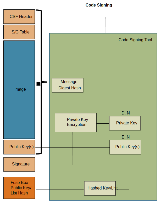
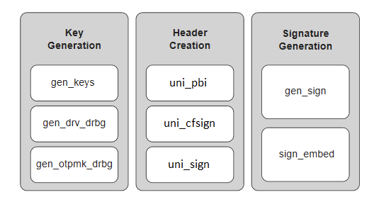
### 9.4 Image Signing
According to the NXP CST tool, the RSA (PKCS#1 format) is supported by CST. Please refer to the link [#4.-code-signing-tool](#4.-code-signing-tool "mention")
One image signing process is shown in the following figure:
#### 9.4.1 uni\_sign
**uni\_sign** tool can be used for the mode that the CSF header generation without signature if a private key is not provided.
According to the [#uni\_sign](#uni_sign "mention"), you should assign a “NULL” value to the `PRI_KEY` field (following figure)
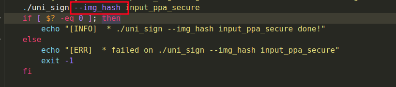
Meanwhile, use the `--img_hash` argument when executing the uni\_sign tool. (following figure)
The image’s `hash.out` in a binary file, the public key's `SRK hash` in the console, and the `CSF header` in a binary file are outputted by the uni\_sign after `./uni_sign --img_hash input_ppa_secure` executed.
#### 9.4.2 Sign Server signing the hash
The image’s `hash.out` in a binary file shall be signed by the signing server or the HSM so that the private key cannot be exported. The HSM signing process should aligned with the C programming:
```c
int crypto_rsa_sign(void *img_hash, uint32_t len, void *rsa_sign,
uint32_t *rsa_len, char *key_name)
{
int ret;
FILE *fpriv;
RSA *priv_key;
/* Open the private Key */
fpriv = fopen(key_name, "r");
if (fpriv == NULL) {
printf("Error in file opening %s:\n", key_name);
return -1;
}
priv_key = PEM_read_RSAPrivateKey(fpriv, NULL, NULL, NULL);
fclose(fpriv);
if (priv_key == NULL) {
printf("Error in key reading %s:\n", key_name);
return -1;
}
/* Sign the Image Hash with Private Key */
ret = RSA_sign(NID_sha256, img_hash, len,
rsa_sign, rsa_len,
priv_key);
if (ret != 1) {
printf("Error in Signing\n");
return -1;
}
return 0;
}
```
The API `RSA_Sign` in the OpenSSL is invoked by the signing process. .
Please distinguish between digest-RSA signing and RSA signing. The `RSA_sign` only use the RSA algo to sign the data and did not calculate the input data hash value, even if you specified the hash type `NID_sha256`.
I have developed a tool to verity the HSM signed image using the public key,
`./verify_tool pskv1.pem sign.out.1 hash.out`
Note, you should assign the PKCS#1 format key. The OpenSSL generated key is PKCS#8 format by default.
```
// To convert from PKCS#8 to PKCS#1:
// $ openssl rsa -pubin -in -RSAPublicKey_out
//
// To convert from PKCS#1 to PKCS#8:
// $ openssl rsa -RSAPublicKey_in -in -pubout
```
### 9.5 image encryption
## 10. Testing
## Terms and Abbreviations
| 名词 | 解释 |
| ------- | ------------------------------------------------------------------------------------------------------------------------------------------------------------------------------------------------------------------------------------------------- |
| CST | 制作secureboot image的工具,参考:[Code Signing Tool](https://docs.nxp.com/bundle/GUID-487B2E69-BB19-42CB-AC38-7EF18C0FE3AE/page/GUID-932D50F3-D90D-4ED0-BEFC-B1BF825EB422.html) |
| OTPMK | fuse上的一个位域,参考:[Program OTPMK](https://docs.nxp.com/bundle/GUID-487B2E69-BB19-42CB-AC38-7EF18C0FE3AE/page/GUID-F780D1D5-F1B2-478B-86AE-267D74F9C790.html) |
| SRKH | fuse上的一个位域,参考:[Program SRKH mirror registers](https://docs.nxp.com/bundle/GUID-487B2E69-BB19-42CB-AC38-7EF18C0FE3AE/page/GUID-D8CC0ABA-108D-4966-8C01-F584B897B9E2.html) |
| SFP | SFP\_INGR寄存器,用于配置FuSe,参考:[Write SFP\_INGR register](https://docs.nxp.com/bundle/GUID-487B2E69-BB19-42CB-AC38-7EF18C0FE3AE/page/GUID-EFF8FF41-C8C0-4A3B-AF95-E801D585B7C6.html) |
| OEM\_WP | OEM阶段fuse上的一个位域,参考:[Fuse Programming Scenarios](https://docs.nxp.com/bundle/GUID-487B2E69-BB19-42CB-AC38-7EF18C0FE3AE/page/GUID-67557564-7BD5-4C5F-9686-59D54A487B88.html) |
| CSFF | OEM阶段fuse上的一个位域,参考:[Fuse Programming Scenarios](https://docs.nxp.com/bundle/GUID-487B2E69-BB19-42CB-AC38-7EF18C0FE3AE/page/GUID-67557564-7BD5-4C5F-9686-59D54A487B88.html) |
| OEM | 原始设备制造商简称\_OEM\_,OEM是英文Original Equipment Manufacturer的缩 |
| POVDD | 芯片上的一个引脚引脚 [Enable POVDD](https://docs.nxp.com/bundle/GUID-487B2E69-BB19-42CB-AC38-7EF18C0FE3AE/page/GUID-0EFF85FB-9070-4D76-A926-B973CA6C8FB5.html) |
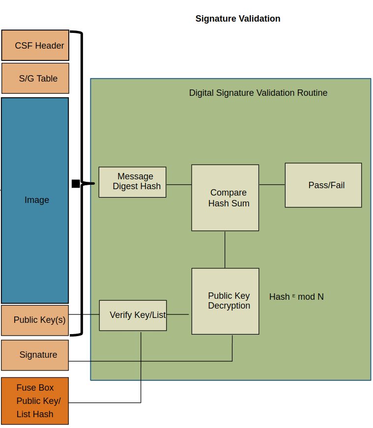
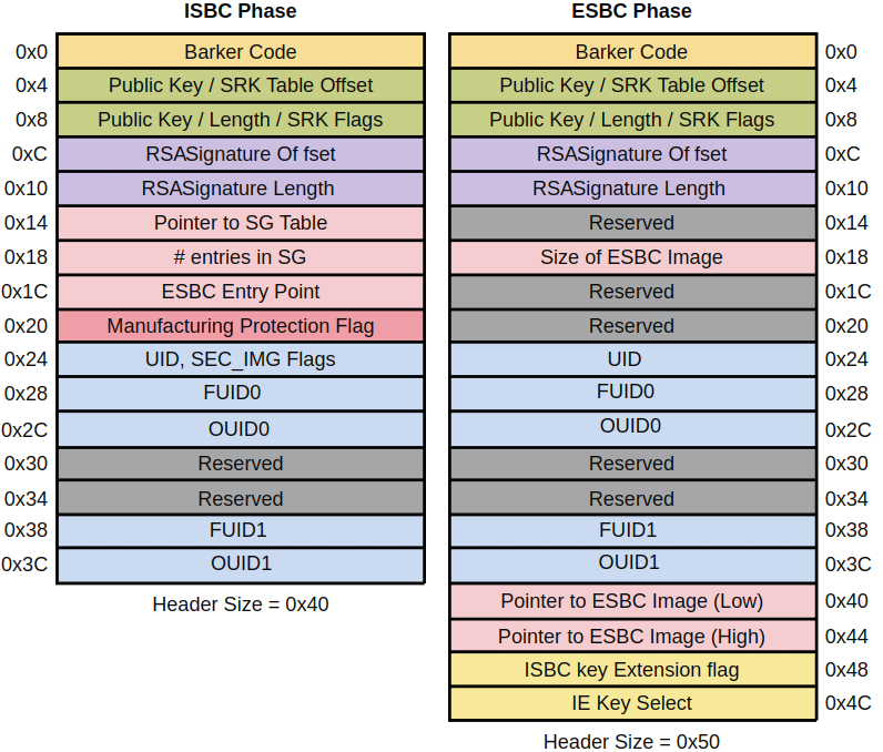
| CSF | NXP Chain of Trust image header 参考: [secure boot - Introduction](https://docs.nxp.com/bundle/GUID-487B2E69-BB19-42CB-AC38-7EF18C0FE3AE/page/GUID-819A6D70-AAED-4B6C-BDA6-7A1B98B77784.html) |
| ISBC | Internal Secure Boot Code,例如bootrom boot code |
| ESBC | External Secure Boot Code,例如uboot |
| ITS | FuSe上的一位,烧写该位代表secure boot使能于产品模式,而不是调试模式。参考: [Secure boot execution flow for Chain of Trust](https://docs.nxp.com/bundle/GUID-487B2E69-BB19-42CB-AC38-7EF18C0FE3AE/page/GUID-FE52492D-CCDA-4B64-A125-04220E4E1811.html) |
| MC | Management Complex firmware, 用于管理内存,LS1046A没有这个固件。 参考: [Management Complex: How DPAA2 objects are created and managed](https://docs.nxp.com/bundle/GUID-87AD3497-0BD4-4492-8040-3F3BE0F2B087/page/GUID-691CA926-7D05-420D-80B5-696FAD7B8923.html) |
| --- | --- |